This thread has been locked.

If you have a related question, please click the "Ask a related question" button in the top right corner. The newly created question will be automatically linked to this question.

LMK05028: The clock output frequency has frequency deviation

Part Number: LMK05028

Dear all:

      I have a customer who is using LMK05028 chip. In the process of use, there is a problem that the output frequency is offset.

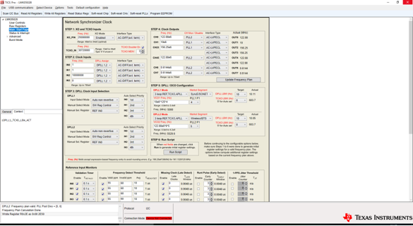
My XO reference is 25M 0.1 PPM; TVCXO control 25M fixed output; TCXO is 30.72 M 0.1 PPM

REF_IN design reference is the 1PPS signal of GPS, but there is no 1PPS signal in normal testing

The current problem is that according to the Settings in the figure above, both 122.88M and 156.25M output clocks have a certain frequency deviation, with a large deviation range.

How to set up adjustment to solve this problem?

Thank  you!

LMK05028_5G_NR_20190904.tcs

  • Hello,

    I cannot see the picture well enough, can you please save and attach the .TCS file?

    Before saving the TCS file.  With the board connected and the outputs not on frequency, can you please goto the "Status & Interrupt" page and press the "Read Status" button so that I may also see the condition of your status bits.

    What is the frequency deviation you are measuring?

    73,
    Timothy

  • Dear Timothy:

            1. I do not have the LMK05028EVM development board, so TICS PRO software cannot implement Read Status

    2. My current practice is to generate the configuration register table of LMK05028 through the setting of Start page and Status&interrupt in TICS PRO, which is imported into the configuration program of STM32 microcontroller, and then written into LMK05028 through SPI interface.
    There are two LED indicators on my board that specify the lock status of output PLL1 and PLL2 by setting Status&interrupt.So far, both lights are on, meaning both are locked.

    3. The current XO input is 25M
    TCXO input 30.72 M
    No input REF_IN

    4. The TCS file of LMK05028 TICS PRO is attached above

    Thank you!

  • Hi Timothy:

         have any suggestions?

    thank you!

  • Hello Timsen,

    Timsen said:
            1. I do not have the LMK05028EVM development board, so TICS PRO software cannot implement Read Status

    Could you readback the bytes wit hthe STM32 microcontroller?  R13/14/15.  However, maybe this is not critical for now... I have another test below which may help understand what is going on....

    Timsen said:
     The current problem is that according to the Settings in the figure above, both 122.88M and 156.25M output clocks have a certain frequency deviation, with a large deviation range.

    Also, I don't quite understand the failure mode yet.  Could you elaborate more on the frequency deviation you measure and if it is fixed frequency (what frequency) or is it oscillating in some fashion?

    --

    Since you have no reference, we expect the LMK05028 to lock to the XO...

    If you set STAT0_SEL (0x2e) = 0x05.(PLL1 N/2), you should measure 25 MHz as your XO is 25 MHz and you have the doubler on.  If you trigger with scope on XO frequency of 25 MHz, is the 25 MHz output PLL1 N/2 fixed in phase to the XO? [another way to confirm PLL1 behavior).

    You can try this also with PLL2 N/2 by setting STAT1_SEL = 0x08 (PLL2 N/2).  If stat0/1 are not accessible, you can set this on the pins you are using.

    73,
    Timothy