This thread has been locked.

If you have a related question, please click the "Ask a related question" button in the top right corner. The newly created question will be automatically linked to this question.

LMK04828: Fpd of PLL1 limit

Part Number: LMK04828

Hi All,

In the LMK04828 design, we tried to accommodate multiple input ref and feedback frequencies and had the Fpd of PLL1 set to 10KHz. But we're having trouble to get PLL1 in lock, the same loop filter setting can get PLL1 in lock if Fpd changed to ~1MHz.

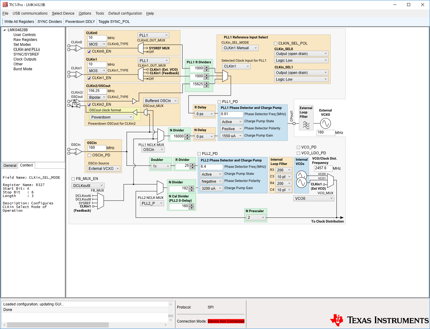
The calculation of loop filter of PLL1 from "PLLatinum SIM" tool was attached, the TICO Pro file also attached.

Could you help to suggest a stable loop filter setting of our case? We need to make decision if the Fpd of PLL1 = 10KHz is doable.

Thanks,

Jin

  • Hello Jin,

    One possibility for the difficulty locking at lower Fpd frequency is that the charge pump may be impacted by VCXO input leakage. The capacitor values in the simulation screenshot are relatively small, and therefore could be quite susceptible to the effects of leakage. If you must operate at a low Fpd frequency, a loop filter which favors larger capacitors might be preferred; consider redesigning the loop filter without fixing the value of R2 in the "Forced Component Values" box, and accept a much lower loop bandwidth (< 25 Hz). It may also be beneficial to buffer the VCXO control voltage through an op-amp or other high-impedance, low input bias current buffer.

    The input clock frequencies you are using in TICS Pro, 10 MHz and 156.25 MHz, have a greatest common factor at 1.25 MHz. Is there another input clock not shown, which further constrains Fpd = 10 kHz? If not, I recommend using Fpd = 1.25 MHz. The higher Fpd allows the loop filter capacitors to be increased, even for narrow loop bandwidths (100 Hz), which reduces susceptibility to charge pump leakage.

    Regards,

  • Hi Derek,

    We expect to use nested 0-dealy mode which have SYS_REF=7.68MHz as a feedback, that's why we have to set the Fpd of PLL1 lower to 10KHz.

    I followed your suggestion and recalculated the loop which have the PLL1 loop as:

    C1=5.6nF, C2=2200nF and R2=470kohm.

    I tried the new values on our board, seems the same scenario as previous filter values. PLL1 can't be in lock if Fpd=10KHz but be in lock with Fpd=1.25MHz.

    If there is extra buffer needed besides of loop filter value changes, we probably need to consider Fpd low limit >=1MHz.

    Thanks,

    Jin


  • Hi Jin,

    It may be the case that the PLL really is locked, but does not meet the reporting accuracy requirement. Refer to equation 3 in the LMK04828 datasheet:

    Input frequency accuracy (ppm) = 1e6 * PLLx_WND_SIZE * FPDx / PLLx_DLD_CNT

    The default EVM configuration sets PLL1_WND_SIZE = 43ns, PLL1_DLD_CNT = 8192. With FPD1=10kHz, input frequency accuracy must be 0.05 ppm. Likely, the PLL cannot report lock with this strict a requirement.

    Is your value for PLL1_WND_SIZE suitable for this low FPD frequency?

    Regards,