This thread has been locked.

If you have a related question, please click the "Ask a related question" button in the top right corner. The newly created question will be automatically linked to this question.

LMK03318: TICS Pro bug while trying to implement frequency plan for LMK03318

Part Number: LMK03318


Hi,

I'm trying to implement 24MHz to 72 MHz frequency conversion with LMK03318.

I'm using TICSPRO 1.6.10.0 and LMK03318_EVM evaluation board

M_divider seems not implemented in TICSPRO for LMK03318. Neither in "PLL" tab nor in "inputs/PLL" tab. (See LMK03318 datasheet p27)

R_divider which is limited to 1-8 range  in "inputs/PLL" tab (as it should be) can be set to 12 in "PLL" tab which let me dream that it would count for a M+R combination ?

But this doesn't work.

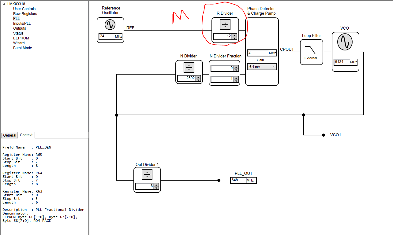
Here is the frequency plan I try to implement (which is valid from the LMK datasheet )

PRIMARY REF : 24MHz
x1_X2 = x1
R_DIV= 1
M_DIV=12
=> PFD frequency = 2MHz
N_divider=2592
=>VCO freq=5184
VCO_OUT_DIVIDER=8
=>648MHz
OUTPUT_DIVIDER=9
=>OUT0=72MHz

Can you help me in any way in order to make the evaluation board work with the desired frequency plan?

Thanks very much for your help

  • Hello Thierry,

    There's a typo in the GUI. The R divider in PLL tab is actually M divider. If you hover your mouse over it and look at the register description in the lower left window you'll see it's "PLLMDIV".

    I'm not sure I understand why you'd want to divide the input, because output phase noise is directly related to PFD frequency. The higher the PFD frequency the better the phase noise. So I'd turn off the divider and use the input doubler to make PFD 48MHz and choose integer PLL.

    Regards,

    Hao

  • Thanks for your answer Hao.

    For information, the first PLL tab shows R (finally M divider with typo error) but not the R register (which exists), but the following tab shows R but not M divider, which is a bit confusing in what finally the software relies on to write the correct registers in the chip.
    I finally ended up making that works, thanks.

    Your question is interesting : I made efforts to make the PFD work around 1MHZ because my previous design was using an AD9522-1 (sorry ;) )

    They document that PFD noise is smaller at a PFD frequency of 1MHz or less :

    NOISE CHARACTERISTICS
    In-Band Phase Noise of the Charge Pump/ Phase Frequency Detector (In-Band Means within the LBW of the PLL)

    At 500 kHz PFD Frequency: -165 dBc/Hz
    At 1 MHz PFD Frequency : -162 dBc/Hz
    At 10 MHz PFD Frequency : -152 dBc/Hz
    At 50 MHz PFD Frequency : -144 dBc/Hz

    I understand from your question that the LMK03318 has different PFD characteristics that make better phase noise results with higher PFD frequency.
    I was not able to find information similar to the one above in the datasheet, can you share more information about that?

    Thank you very much!

    Thierry

  • Hello Thierry,

    I don't know why they said that, but this is based on PLL theory and it is kind of obvious to observe on a phase noise analyzer that the higher the phase detector frequency the better the PLL flat phase noise. And this applies to any PLL.

    You can refer to any PLL book for more details in the theory.

    Regards,

    Hao

  • OK I had a look at their datasheet. Their statement is true but there's some misunderstanding. The numbers that they list are phase detector noise, not output phase noise. Output phase noise = PLL_FOM + 20logN + 10log(fPD)

    So if phase detector frequency is increased, then yes phase detector noise is increased in the scale of 10log, but noise contributed by N divider is decreased in the scale of 20log. since output frequency is constant, N*fPD is constant. That's why total output phase noise is decreased with the increase of PFD frequency.

    Regards,

    Hao