A related question is a question created from another question. When the related question is created, it will be automatically linked to the original question.
If you have a related question, please click the "Ask a related question" button in the top right corner. The newly created question will be automatically linked to this question.
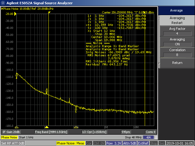
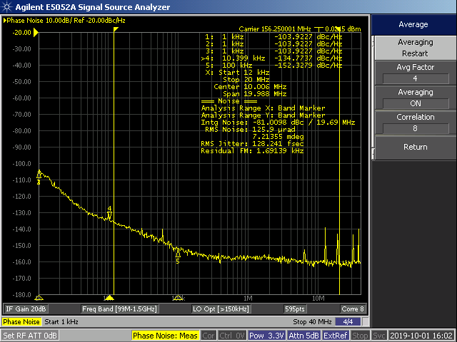
The crosstalk spurs between 156.25 MHz and 25 MHz (at multiples of 6.25 MHz) will be quite aggressive, see below. Ideally, outputs where the GCD frequency is in the jitter integration bandwidth should be separated as much as possible. I don't recommend placing 25 MHz next to 156.25 MHz unless the performance degradation on the 156.25 MHz output is acceptable.
Apologies for the delay. Placing 25 MHz on PLL2 does not improve the crosstalk, as the crosstalk is mostly seen at the output stages in the IC. And you are correct, PLL2 has a higher noise floor, so the 25 MHz signal jitter is worse with no change to the spurious behavior.