This thread has been locked.

If you have a related question, please click the "Ask a related question" button in the top right corner. The newly created question will be automatically linked to this question.

LM567C: trying to get this to trigger once it gets to 35hz but its triggering from 0 to about 30

Part Number: LM567C

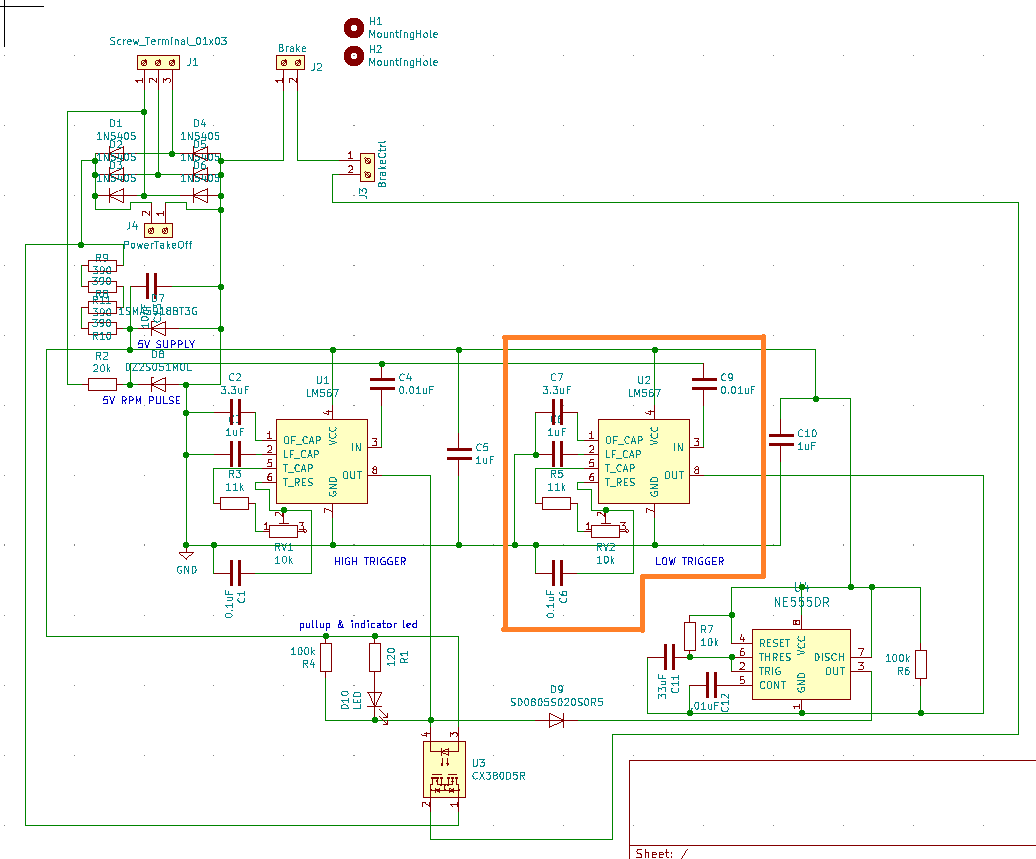
I'm trying to get this to trigger once it gets to 35hz but its triggering from 0 to about 30 from what i can tell

I tried to set it up so the frequency window is the max (14%) and when the potentiometer is centered the target frequency is 64hz. 64*.86=55

So at centered position i shouldnt get a low signal from the device until 55hz but for some reason it is triggering far before that and shutting off before 55

the input is alternating between 0 and 5v

screw terminals are a 3 phase 80v generator connection, intended operation is output of the LM567C to go low once the generator is at high speed ~ 35hz  but the output is low as soon as the generator starts then goes high after the speed increases.

The specific circuit is boxed in orange, entire schematic provided for reference.

  • Here's a capture of the 5v RPM pulse trace, significantly less clean than I had anticipated. disregard the y scale, it's not meaningful from this device. from the spec of the zener diode the peaks are at 5volts. running the numbers on this the frequency is 44hz. the question is are those blips at the upward zero cross also being sensed as an additional cycle?

  • Hello,

    I don't quite understand the schematic. Even with the max potentiometer value, center frequency is 1.1/(21e3*0.1e-6) = 523Hz. Not sure how 35Hz is derived. And yes the glitch around the threshold can confuse the input detection circuit.

    Can you start with sanity checks using a signal generator?

    Regards,
    Hao

  • Somehow that math error has gone uncaught for quite some time, i've been using 1uF in the calculations it seems. Accounting for the 14%bandwidth the lowest frequency that can be detected is 440Hz, hopefully i've done that chuck of math correctly. even with the incorrect capacitor (ill swap it once this stops detecting low frequencies) its triggering far lower than expected. I'll test with a square wave generated from an arduino and report back with the findings.

  • Hi Jake,

    I'll close this thread for now. You can reopen it once the test is done.

    Regards,
    Hao

  • after swapping the capacitor to the proper value (1uF) the chip behaves as expected. simple mistakes seem to creep up once in a while. thanks everyone that assisted!