This thread has been locked.

If you have a related question, please click the "Ask a related question" button in the top right corner. The newly created question will be automatically linked to this question.

LMX2595EVM: LMX2595EVM

Part Number: LMX2595EVM
Other Parts Discussed in Thread: LMX2595,

Hello sir,

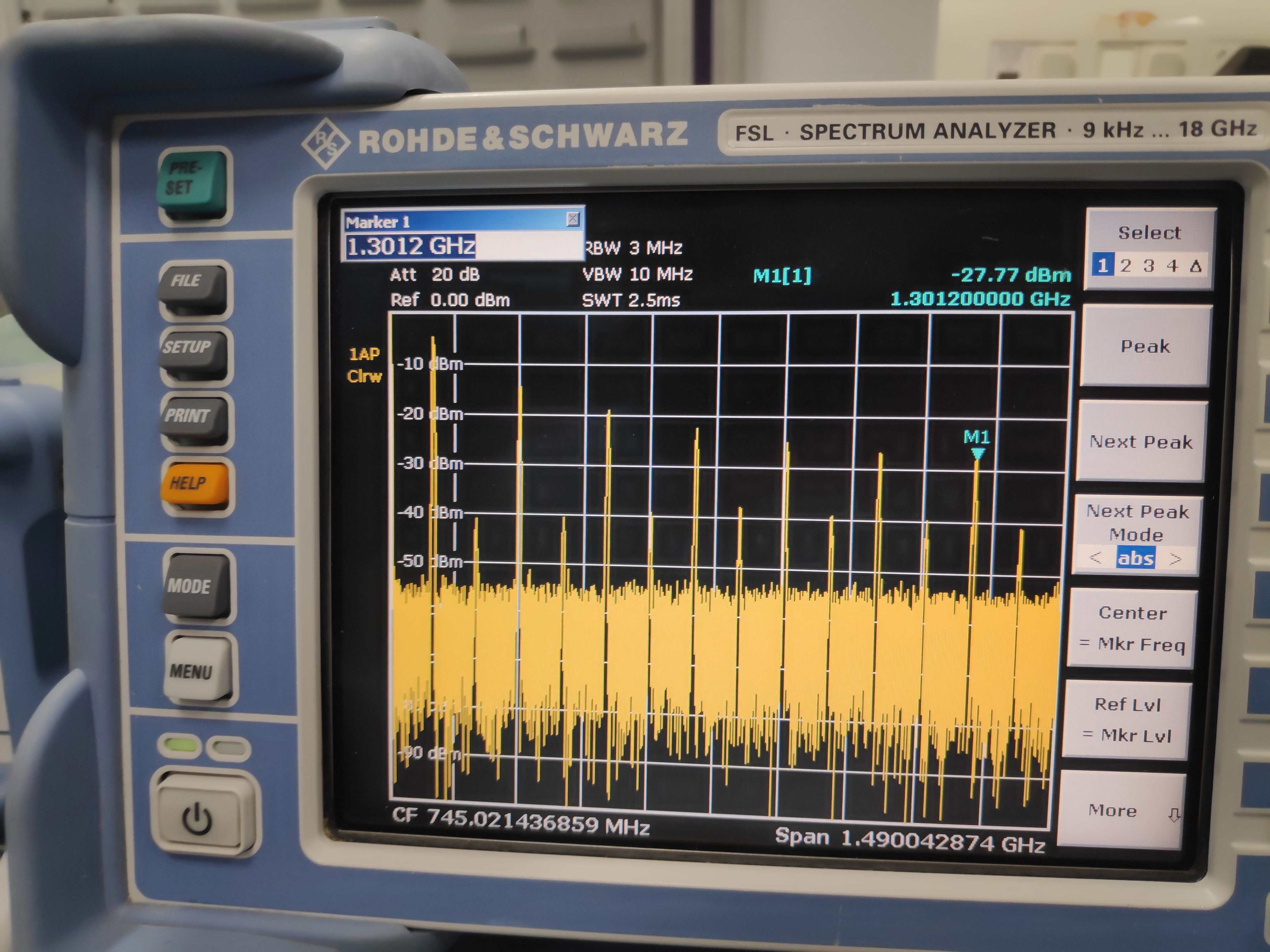
            I am using LMX2595 EVM, to generate 17GHz signal over 200MHz Bandwidth. I have generated 100 MHz by using reference pro board wherein i am getting harmonics at the output of the reference pro board. I don't know why my PLL is not locking. Even the lock detector is not blinking in EVM. The output of the LMX2595 EVM is also having harmonics at 4.2GHz, 8.5GHz, when I am trying to generate 17GHz. I tried feeding the reference input to the LMX2595 EVM from external source with no harmonics. As far as my knowledge I think it is due to the PLL which is not locking. Please let me know the necessary changes required.

  • Hi Singam,

    First of all, please use the Default Mode to ensure it works. Then change the VCO to 8500MHz and ensure it is again locked. 

    After that, change the A channel mux to VCO Doubler; check the VCO2X_EN bit; change B channel mux to SysRef (this will disable the channel divider). Finally, uncheck the SEG1_EN bit. 

    With Ref Pro as the reference clock, we have seen LMX's output has multiple 100MHz spurs. You may try with an external reference clock source to verify again.

  • Thanks for the quick response Sir, But I had tried and have few more questions


    1) Even after loading in the default mode the PLL is not locking. The output is not stable at 7GHz but the lock detector LED is ON. For the frequencies upto 2GHz the output is stable.  

    2) I had checked the communication and everything was fine, But I don't know why the behavior is poor at higher frequencies. 

    3) The tuning voltage to the VCO is same for all the frequencies. As per my knowledge the VCO output frequency changes based on input tuning voltage. (As loop filter configuration is same in all the cases).

    4) How can you claim that the designed loop filter works for the entire frequency range when it is designed for 15GHz. Even though there are different VCO cores available. 

    I have attached video when the PLL is configured in default mode. 

    kindly let me know the changes required in the hardware to get the stable output.

    thanks in advance. 

  • Hi Singam,

    Does your EVM come with an on-board 100MHz XO?

  • Yes the EVM has on board 100MHz XO on it. I had tried using the reference signal 100MHz from ref pro board (which has even and odd harmonics) and from the signal generator (clean and stable 100MHz). In both the cases the output is not stable.

    Thanks in advance   

  • Hi Singam,

    Did you remove the power supply of the XO and change the resistor network to make it accept external reference clock source?

  • I am sorry sir, I haven't done that. I have supplied 3.3V & 600mA to the EVM as per the user guide.

    1) Could you please tell how to disable the on chip XO oscillator and changing the resistor network to accept it to make use of external oscillator.

    2) No where I am finding how to disable the on chip XO oscillator.

    Thanks in advance.

  • Hi Singam,

    Do you have the EVM user's guide (SNAU219, no suffix)? Go to Appendix D, you will see the details.

  • Yes sir I have seen it, But as per the appendix d in the user manual it is recommended to connect the resistor R24b to the OSCin path. Do I need to short the path by wire or what. All the tracks are made and I don't think so I need to make any further connections. Kindly let me know sir and elaborate. I am running out of time.

    Thanks in advance

  • Hi Singam,

    Please follow the suggestion in Appendix D. Shown below is the modification for external single-ended input. Either OSCinP or OSCinM could be connected to an external clock source.

  • Thank you sir! I have seen this schematic earlier but the tracks (connections) which are made on the board.

    1) How do I manually remove the connections on the EVM Board which are already made from R33 to Vcc, R24b to pin 5 of on chip oscillator, and so on... In order to connect external source.

    Kindly let me know the process  to remove these connections which are already made.

    Thanks in advance

  • Hi Singam,

    You need a soldering iron to remove or add those components.

  • When you were testing the LMX2595EVM have you used the reference signal from the on chip oscillator or else from the external source.

    1) If it is from the external source then did you de-soldered the resistor in order to change the resistor path. I don't think so to de solder the components as the soldering  is very minute. 

    2) Do you have testing results other than the data which is in EVM's user guide.

  • Hi Singam,

    This product has been out to the market for almost two years, we have tested the EVM thousand times with both external clock source and the on-board XO. 

    The reference clock pays an important role to the synthesizer's performance, we cannot use jumper and header to switch between on-board and external clock. Some hand-on soldering works are required when we change the clock source, this is not difficult.