


Part Number: LMX2595
Hi team,
My customer is using TI's LMX2595 series PLL. During the use, it is found that the loop characteristics of enabling and disabling OSC_2x are different.
When FOSC = 100MHz, osc_2x = 2x, FPD = 200MHz, the loop characteristics are shown in Figure 1;
Set FOSC = 200MHz, osc_2x = 1X, FPD = 200MHz, and the loop characteristics are shown in Figure 2.
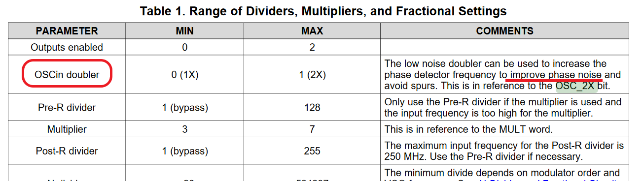
The FPD frequency set in these two cases is the same. When the spectrometer is adjusted to span = 500KHz, it can be seen that the loop using the oscin doubler function drops smoothly; the loop without the oscin doubler function will have obvious depression. Judging from the function of oscin doubler, it can improve phase noise, but is the phase noise performance better in Figure 2 (osc_2x = 1x)? Why is that
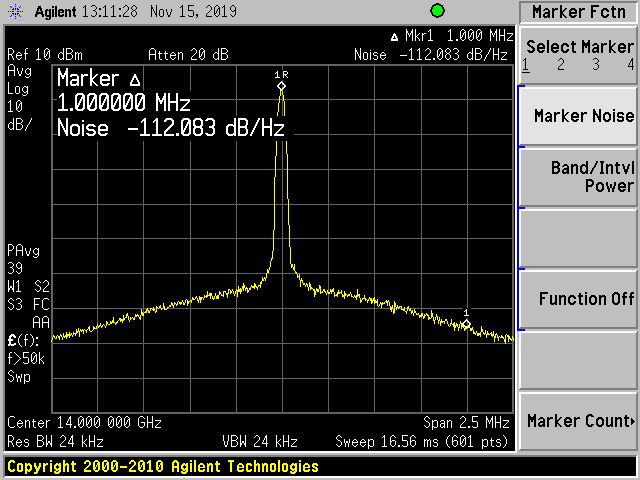
Figure 1 FOSC = 100MHz, osc_2x = 2x, FPD = 200MHz
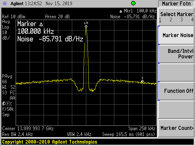
Figure 2 FOSC = 200MHz, osc_2x = 1X, FPD = 200MHz
Best Regards,
Amy Luo
