This thread has been locked.

If you have a related question, please click the "Ask a related question" button in the top right corner. The newly created question will be automatically linked to this question.

CDCI6214: I2c live programing problem

Part Number: CDCI6214
Other Parts Discussed in Thread: CDCE6214-Q1

Hi,

Our products have many different configurations, we should live program CDCI6214.

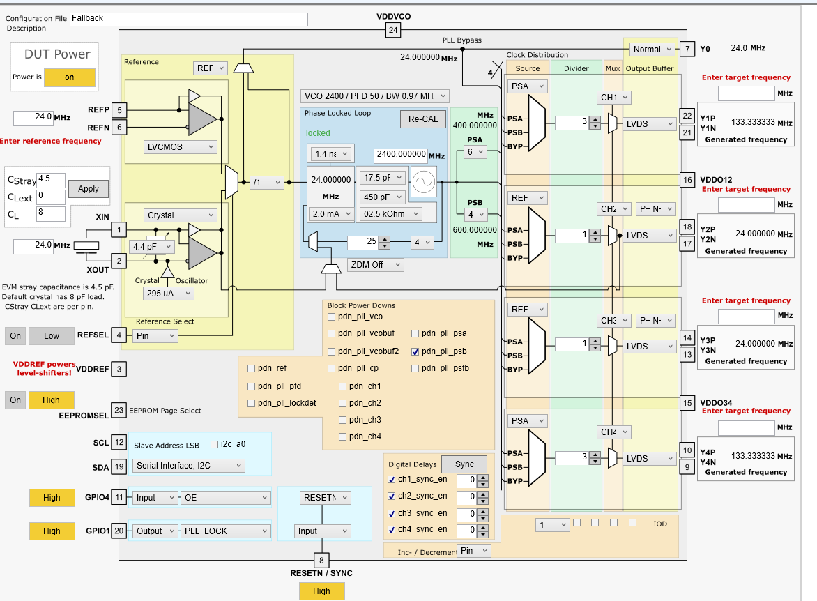
During production, we found that some devices , the PLL is unlock as shown in the figure below. but other configurations are work .

We checked that the input signal was normal. And then ,We put this chip on the EVM board, and the problem remains.

As  the figure below,

    step1. write all register , PLL is unlock

    step2. Press "Re-Cal" , PLL is also unlock

    Oscilloscope test out that all 24Mhz is out put normal, all 148.5Mhz  is abnormal.

        Our configuration is refer to the datasheet. 

        Are there any problems in the following processes?? 

step1.  ee_lock

step2.   ch[4:1]_1p8vde 

step3.   Program register addresses in descending order from 0x44 to 0x00

and we have step4.   "RE-CAL" the PLL

  • Hello,

    I quickly tried your setting on the bench and the PLL is locked. 

    Attaching the config file that I used: 

    R70	0x00460000
    R69	0x00450000
    R68	0x00440000
    R67	0x00430020
    R66	0x00420200
    R65	0x00410F34
    R64	0x0040000D
    R63	0x003F4210
    R62	0x003E4218
    R61	0x003D1500
    R60	0x003C0018
    R59	0x003B1061
    R58	0x003A0008
    R57	0x00398851
    R56	0x00380405
    R55	0x00370003
    R54	0x00360000
    R53	0x00358000
    R52	0x00340008
    R51	0x00338861
    R50	0x00320425
    R49	0x0031C001
    R48	0x00300000
    R47	0x002F8000
    R46	0x002E0008
    R45	0x002D0851
    R44	0x002C0405
    R43	0x002BC001
    R42	0x002A0000
    R41	0x00298000
    R40	0x00280008
    R39	0x00270851
    R38	0x00260409
    R37	0x00250003
    R36	0x00240000
    R35	0x00238000
    R34	0x00220050
    R33	0x00210007
    R32	0x00200000
    R31	0x001F1E72
    R30	0x001E514A
    R29	0x001D8129
    R28	0x001C0000
    R27	0x001B0010
    R26	0x001A8A1C
    R25	0x00192406
    R24	0x00180000
    R23	0x00170000
    R22	0x00160000
    R21	0x00150000
    R20	0x00140001
    R19	0x00130000
    R18	0x0012FFFF
    R17	0x001126C4
    R16	0x0010921F
    R15	0x000FA037
    R14	0x000E0000
    R13	0x000D0000
    R12	0x000C0000
    R11	0x000B0000
    R10	0x000A0000
    R9	0x00090000
    R8	0x00080001
    R7	0x00070C0F
    R6	0x000619CA
    R5	0x00050028
    R4	0x00040055
    R3	0x00030800
    R2	0x00020050
    R1	0x00016924
    R0	0x00001004
    

    You can load this file by "File" -> "import hex registers".

    Regards,
    Hao

  • Hi,

    Total 400 devices , we found that 10% CDCI6214 PLL was unlock. We put these chips on the EVM board, and the problem remains , was unlock.

    Replace the aulty chips .the NG deivce's  PLL was lock..

  • Hi

    I upgrade "TICS Pro",   The config file also unlock...

  • Hi

    I upgrade "TICS Pro",   The config file also unlock...

  • HI,

    the new "TICS Pro"  6214 FOD function was gone ???

  • Yes we de-featured the FOD because we've received and verified reports of failure at certain frequencies, and there wasn't a way around it. The datasheet revision and PCN are in process, if not done yet. 

    If you need fractional dividers, please use CDCE6214-Q1 instead. It's pin compatible with CDCI6214.

    Regards,
    Hao

  • If you are starting up from EEPROM and it doesn't lock, then the problem is probably due to RESETN pin. A 4.7kOhm pull up resistor as well as a 0.47uF cap to ground are needed, in order to delay the ramp time of this pin (by > 2.5ms), so that it doesn't reach the final value before VDDREF does.

    Regards,
    Hao

  • Hi,

    Because of so many different configurations  , we have to live program.

    if write configuration to EEPROM,   EEPROM cannot be broke up ??

    EEPROM programing cycles only 10,000 cycles...

  • OK if you use live I2C then you don't need to worry about RESETN pin. When you say 10% of PLLs don't lock, do they unlock at the same frequency setting that you showed previously? Can you load the register file that I attached file and see if it works? Write a '1' to "swrst" bit at last to do a software reset.

    Regards,

    Hao

  • R70 0x00460000
    R69 0x00450000
    R68 0x00440000
    R67 0x00430020
    R66 0x00420000
    R65 0x00410F34
    R64 0x0040000D
    R63 0x003F0210
    R62 0x003E4209
    R61 0x003D1500
    R60 0x003C0018
    R59 0x003B106B
    R58 0x003A0008
    R57 0x00390A65
    R56 0x00380405
    R55 0x00370003
    R54 0x00360000
    R53 0x00358000
    R52 0x00340008
    R51 0x00330A65
    R50 0x00320415
    R49 0x0031C001
    R48 0x00300000
    R47 0x002F7600
    R46 0x002E0008
    R45 0x002D0A65
    R44 0x002C0415
    R43 0x002B0003
    R42 0x002A0000
    R41 0x00298000
    R40 0x00280008
    R39 0x00270A65
    R38 0x00260405
    R37 0x00250003
    R36 0x00240000
    R35 0x00238000
    R34 0x00220050
    R33 0x00210007
    R32 0x00200000
    R31 0x001F1E72
    R30 0x001E5142
    R29 0x001D8129
    R28 0x001C0000
    R27 0x001B2410
    R26 0x001A0718
    R25 0x00190000
    R24 0x00180001
    R23 0x00170000
    R22 0x00160000
    R21 0x00150000
    R20 0x00140000
    R19 0x00130000
    R18 0x00120000
    R17 0x001126C4
    R16 0x0010921F
    R15 0x000FA037
    R14 0x000E0000
    R13 0x000D0000
    R12 0x000C0000
    R11 0x000B0000
    R10 0x000A0000
    R9 0x00090000
    R8 0x00080000
    R7 0x00070000
    R6 0x00060000
    R5 0x00050020
    R4 0x00040055
    R3 0x00030000
    R2 0x00020050
    R1 0x00016822
    R0 0x00001000

  • yes,

    only at this configuration 

  •      Write a '1' to "swrst" bit at last  , and read all reg, found that  the config rollback to this??

         PLL vco was 2400Mhz...?

  •  Hi,

          In our other series of products, it is found that if EEPROM is written multiple times, SDL will be permanently pulled down. Is this chip broken down?

  • Hello,

    If EEPROM pages are selected, then writing a '1' to swrst bit will bring the device to EEPROM settings. It retains the previous register setting only if the device is in fallback mode, i.e., EEPROM = Mid and REFSEL = mid.

    Alternatively, use bit "recal" to re-calibrate VCO.

    When SDL / SDA are not working, it's possible that register MODE is written as pin mode, in which case SDL and SCA work as GPIO pins. SDL and SDA should always function well when device is in fallback mode.

    Regards,
    Hao

  • Hello, Hao Z

     Is there any test problem with our register configuration??

  • Hello,

    Last time I checked the configuration works fine. Just to confirm, the failure only happens at 10% of the chips, and if the suspect chip is replaced then the board works fine? 

    Regards,
    Hao

  • Hi

    Yes !  Replaced  the suspect  chips, it works fine.

  • OK then I've let the FAE to help ship 3 - 5 parts to myself for debugging. We'll contact by email moving forward.

    Regards,
    Hao

  • And meanwhile, a quick fix would be to replace the part with CDCE6214-Q1.

    Regards,
    Hao

  •   HI. 

    TICS Pro  CDCE6214Q1 FOD was "RSVD"

    Are there any software upgrade??

  • Closing this thread. Will continue through emails.

    Regards,
    Hao