


Other Parts Discussed in Thread: LMX2595
Hi,
Hello folks, I have a question about input reference clock for LMX2595.
In my application, we want to use external input reference clock for synchronization. However, I am quite confused about the requirement for input reference clock.
The figure below shows the requirement according to datasheet:
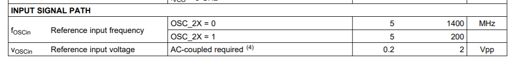
In our case, we have a 400MHz clock as input reference. In previous experiment, our clock is a relatively clean square wave. The Vpp of clock can go up to 300mV. Based on our testing, we found that LMX2595 can lock even if Vpp is reduced to 30mV. The board outputs desired frequency and lock LED is green.
After that, we made some adjustment to our system, the input reference clock is still 400MHz but its shape is not a square wave and Vpp is lower, as shown below:
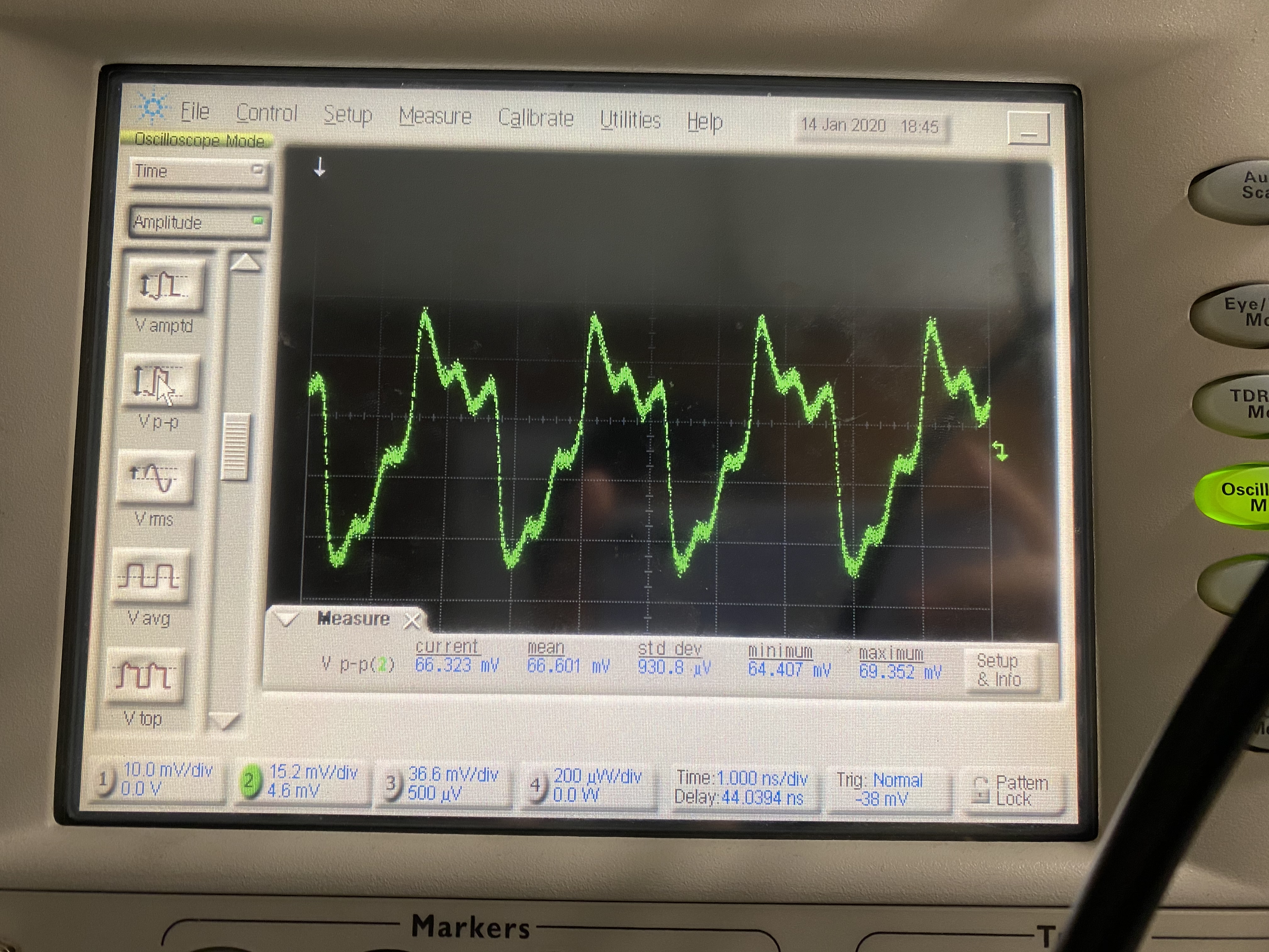
We found that LMX2595 can not lock in this case. Do you have any idea why it happens? Is LMX2595 sensitive to the shape of input reference clock?
Can you give us any suggestion?
Regards
Axel