This thread has been locked.

If you have a related question, please click the "Ask a related question" button in the top right corner. The newly created question will be automatically linked to this question.

CDCE925 not ACKing I2C transfers

Other Parts Discussed in Thread: CDCE925, CLOCKPRO

Hi guys,

I've put together a CDCE925-based oscillator on a Roth Elektronik TSSOP16 prototyping board. This consists of the chip, a 13.876MHz crystal, and a bunch of wires. The programmer I'm using is a homebrew version of the TI CDCE925 Performance Evaluation Board programmer (page 24). I2C pullups are 2x10k to 1.8V (though I've tried 3.3V as well).

The problem I'm having is that while ClockPro can see the programmer pod -- there are start pulses and address bytes going over the I2C bus -- the chip isn't ACKing the address bytes. This means ClockPro doesn't list it as an available chip -- or rather it tells me that I should pull VDDOUT to ground. I have already done this (in fact, I've tried grounding and connecting to +3.3V) and the chip is still ignoring everything I send it.

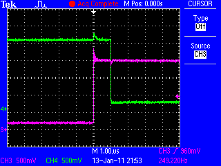
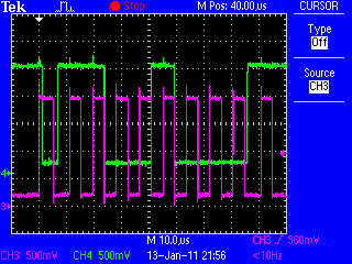
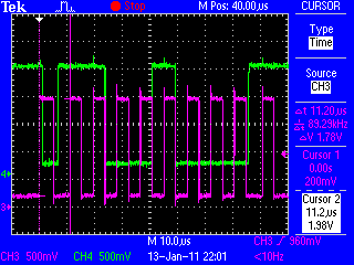
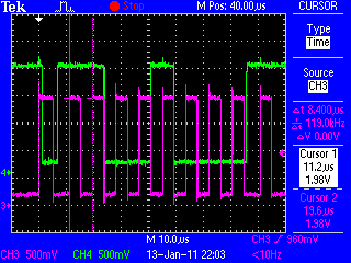
I've checked the signalling on my scope (200MHz Tek TDS2024B DSO) and it looks fine -- nice square edges, minimal ringing/overshoot/undershoot. I measured the bus clock frequency at about 120kHz.

All grounds and power lines are stable, and the power looks good (1.8V on VDD, provided by a NatSemi LP5951MF-1.8, 3.3V provided by my bench PSU).

I've even tried swapping SDA and SCL, and tried a new chip. Zilch, zip, nada.

Does anyone have any idea what might be going on here?

Thanks,
Phil.

  • Phil,

    If you have managed to create an I2C sequence with the clockPro that means that you changed your PC to a 32 bits environement one and that currently you are communicating with the FTDI chip. For a lack of acknowledgement there are many reasons. For more information on missing acknowledgements you can check the following application notes:

    http://focus.ti.com/general/docs/litabsmultiplefilelist.tsp?literatureNumber=scaa105

    http://focus.ti.com/general/docs/litabsmultiplefilelist.tsp?literatureNumber=scaa106

    I would change the last two bits of the slave address in case the default one of the device connected is not the same as the default in the TI clock pro.

    Best regards,

    Mariajose 

  • mapefer3 said:

    If you have managed to create an I2C sequence with the clockPro that means that you changed your PC to a 32 bits environement one and that currently you are communicating with the FTDI chip. For a lack of acknowledgement there are many reasons. For more information on missing acknowledgements you can check the following application notes:

    Indeed I have -- I found an old IBM T42 ThinkPad with a working 32-bit Windows XP SP3 installation, and used that. That got the FTDI chip to send I2C commands, but the CDCE925 isn't ACKing (as seen on my oscilloscope).


    mapefer3 said:

    I would change the last two bits of the slave address in case the default one of the device connected is not the same as the default in the TI clock pro.

    ClockPro does that already, doesn't it? (and if it doesn't, it probably should). In any case, I have VDDOUT grounded -- even if the EEPROM has somehow gotten mangled (which seems unlikely), the chip should have S1 and S2 set to I2C mode, using the default address.

    I doubt the pullups are the issue: an ACK is caused by the slave device pulling SDA low at the 8th bit. If my pullups were too weak, I'd be seeing a poor high (idle voltage too low); if they were too low, the FTDI + level translator wouldn't be able to pull the bus low enough. In this case, I'm not seeing any evidence of the 925 even trying to pull the bus low (see SCAA106 page 3, figure 2 and note the change in LOW level on SDA just to the right of the centre line -- I don't see this with my design).

    Thanks,

    Phil.

  • Hi Phil,

    Hi Phil,

    The TI Clock pro does poll all 4 possible slave addresses when you click on the button "refresh devices". If after clicking "refresh devices" button on the GUI the LED in the GUI does not go green, that means that the FTDI chip could not communicate or detect the CDCE925 in any of the possible slave addresses.

    When your board was plugged the first time to your PC, did it ask you for drivers? if you had already installed the TI clock pro, then it is important to enter manually on the windows wizard teh location c:\windows\system32 so both .inf and .sys files can allow the driver for the FTDI to be installed properly for this application.

    By setting Vddout=GND when SPICON=1 it will allow I2C communication through S1 and S2, but that would not be needed if the device has its default EEPROM

    Please send me a screenshot of the SDA and SCLK signals going to the CDCE925 so we can see if it is a problem of timing in the I2C signals.

    Best regards,

    Mariajose


  • mapefer3 said:

    The TI Clock pro does poll all 4 possible slave addresses when you click on the button "refresh devices". If after clicking "refresh devices" button on the GUI the LED in the GUI does not go green, that means that the FTDI chip could not communicate or detect the CDCE925 in any of the possible slave addresses.

    That's exactly what's happening. I can plug the FTDI chip in, hit Refresh, then I see a bunch of I2C START/ADDRESS sequences; the FTDI tries each address for a couple of seconds, then moves onto the next. If there was a problem with the drivers, I'd expect to either not get any activity on the I2C bus, or for the application to crash...

    mapefer3 said:

    By setting Vddout=GND when SPICON=1 it will allow I2C communication through S1 and S2, but that would not be needed if the device has its default EEPROM

    Indeed -- but it seemed like a good idea (if only to cover the possibility of a garbage-write having corrupted the EEPROM).

    mapefer3 said:

    Please send me a screenshot of the SDA and SCLK signals going to the CDCE925 so we can see if it is a problem of timing in the I2C signals.

    Will do this when I get back to my workbench -- shouldn't be too hard to get a couple of screen dumps with timing data.

    Is there any way to tell ClockPro to slow the I2C bus down, maybe down to as low as a few kHz?

  • As promised, here are the scope traces. Magenta (Ch3) is clock, green (Ch4) is data.

    Setup time during START event

    Entire bus cycle

    Measure frequency of SCK during START event -- about 89.3kHz

    Measure frequency of SCK during data transfer -- 119kHz

    Measure time between rising edge of SCK and falling edge of SDA. 1.6us.

    The start timing looks a bit suspect to me -- there isn't much of a delay between SCK going high and SDA going low (a start being defined as a H->L transition on SDA while SCL is high). I'd have expected the transition to sit roughly in the middle of the 'high' part of the SCL pulse.

    Clock frequency is also a little high (120kHz vs the specified max of 100kHz for Standard Speed mode).

    Hmm.

  • I think I may have found a solution...

    I tried hooking the CDCE925 up to a Microchip PIC18F2520 last night, and used the PIC's Master/Slave Synchronous Serial Port module to drive the I2C bus. The CDCE' acknowledged the address byte and responded as expected. After taking a long look at the data traces from both the FTDI FT2232 and the PIC, I came to the conclusion that the FTDI chip was violating the hold time requirement for SDA -- that is, SCL was going low after the next bit had been loaded into SDA.

    I also noticed that the FTDI wasn't pulling to ground properly. This was fixed by enabling High Current I/Os using FT_PROG. You need an EEPROM attached to the FTDI chip for this to work.

    To deal with the timing issue on SDA, I added 1nF of capacitance between SDA and GND. The CDCE925 EVM ("Page 24") schematic shows a 220pF capacitor, though in my experience this was insufficient.

    After increasing the capacitance and enabling High Current I/O, the CDCE925 is communicating with the PC perfectly. I've just programmed one to PLL a 13.875MHz crystal up to 97.125MHz for my Digital Data Separator chip.

    Would it be possible to have external programmer support in the next version of ClockPro, or at least support for a different I2C Host Adapter (e.g. the TotalPhase Aardvark). The FTDI chip seems marginal at best... Failing that, perhaps you could release details of the algorithms ClockPro uses to find PLL settings?

    Thanks,
    Phil.

  • HI Phil,

    We do have available a programming EVM (http://www.ti.com/litv/pdf/scau026a), so you can place your device in the socket. There is a tool under the main Menu of the clock pro that allows you to communicate with that programming EVM.

    Best regards,

    Mariajose


  • Unfortunately it seems the 9xx Programming EVM isn't stocked by DigiKey, Farnell or Mouser... :(

    I've managed to get Clock Pro to (sort of) behave itself by setting "compatibility mode" (in the right-click properties for the desktop shortcut) to "Windows XP SP3". It still flakes out on occasion, but it works well enough to program the chips.

    A 1n5 capacitor (ran out of 0805-package 1nFs) from SDA to the ground plane sorted out the hold time violation.

    Now I just need to fix the decoupling on the test board -- it's refusing to be programmed if VDDOUT is at 3V3 (it works if VDDOUT is open or grounded). It looks like there's a lot of noise being fed back into SDA and SCL from the power supply or the PLL outputs... Not really surprising when you consider that it's point to point wired, I'm surprised it managed to produce a recognisable output at 97.1MHz in such conditions!

    No doubt about it, as long as you respect the I2C hold conditions, it's a very nice chip, especially for CPLD/FPGA clocking. I'll be keeping a few in my spares box!