This thread has been locked.

If you have a related question, please click the "Ask a related question" button in the top right corner. The newly created question will be automatically linked to this question.

NE555: How do I create a biphasic square wave generator circuit with variable frequency and magnitude?

Part Number: NE555
Other Parts Discussed in Thread: CD4017B, TLC555, TLV172, LM358, LF347, LF353

I read somewhere that a single NE555 would not be able to create a biphasic square wave, only monophasic. I am wondering whether that is possible. If not, how do I connect two NE555 timers to create a biphasic square wave?

  • Kiryl,

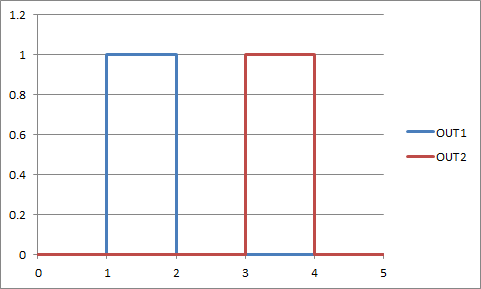
    Is this the signal that you want? What are the time periods for each step?

  • Kiryl,

    The time periods can be ratios, such as all steps are the same width (1:1)  If the ratios can fit into 10 time steps or less then CD4017B can team up with a single NE555. The NE555 sets the repetition rate (output frequency). The CD4017B sets the output phases.

    If all steps are the same width, then connect OUT4 to RESET and OUT 1 and OUT 3 can be the bi phase outputs at 1/4 the NE555 frequency.

  • Hi Ron,

    Thanks for your reply. 

    It was difficult to follow you since my knowledge of circuits is comparable to that of an introductory circuits college course, with cursory knowledge of ICs, op-amps, and microcontrollers.

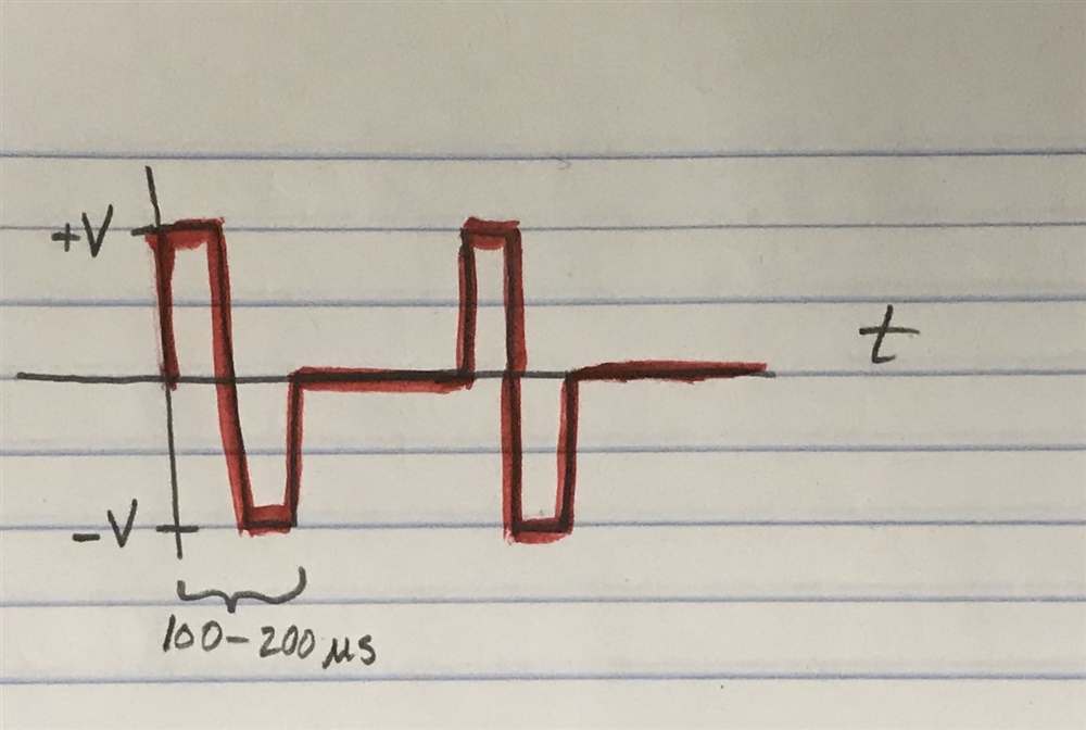
    Having said that, the drawing of the waveform you sent in the previous post is not what I want. I included a picture of the waveform I am looking for below.

    More specifically, I am looking for variable frequency (20-35 Hz) and variable pulse width (100-200 us). Variable amplitude would be nice as well, but I think an op-amp with a potentiometer connected to the circuit would get the job done, right?

    Anyways, I hope you are able to help out.

    Thanks in advance,

    Kiryl

  • Kiryl,

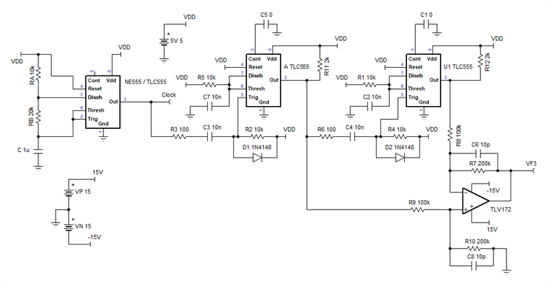
    Here is a circuit that should do what you requested.

    TLCorNE555.TSC

    RB sets frequency. 1.44/(C*(2*RB+RA))

    R5 set positive pulse time. 1.1*R5*C7

    R1 set positive pulse time. 1.1*R1*C2

    R7,R10 sets the voltage gain(s)

    If NE555 timer is used, then R3, R6, D1, and D2 are optional

    If TLC555 timer is used then R11, R12 are optional

    Is the adjustable feature "set it and forget it" or set it over and over again?

  • Ron,

    Thanks so much for your schematic! This is well beyond what I anticipated.

    I will try to build and test this circuit, first virtually and then physically.

    The frequency will likely be "set it and forget it" once I find the optimal one.

    The amplitude and pulse width will need to be varied every once in a while.

    Do you recommend using TLC555 over the NE555 if I can get my hands on one?

    Thanks again,

    Kiryl

  • Kiryl,

    TLC555 would be a little better as the output high voltage is more predictable.

    I have a couple component changes.

    C3, C4 = 2.2nF (to make sure trigger pulse is shorter than output pulse) 

    C5, C1 = 10nF (this helps protect against supply noise)

  • Hi Ron,

    I have a few other questions.

    Can I use an LF351 or LM358 op-amp instead of the TLV172 shown on the schematic?

    What is the clock output wire on the first timer IC and do I need it to test the circuit?

    This might be a basic question, but to test the circuit using an oscilloscope, would I simply connect the VF3 pin across a load resistor to ground and measure across the load?

    Thanks for all the help,

    Kiryl

  • Kiryl,

    Clock output "wire" is just test point / informational. It doesn't do anything.  Just measure the VF3 node with a oscilloscope , no load is needed because the output is a voltage signal. 

    LM358 would work but the edges would be much slower. LF353 or LF347 is slower, but just a little bit.