Part Number: LM567C
Hi
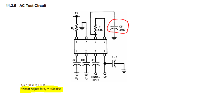
I have an LM567C on the test bench running as an oscillator (Figure 18). R1=2.4k 1%, C1=3.2n, C2=(any value between 4.7n and 10n). Fo = 137.5Khz.
This is configured as an oscillator. Is there a specific value I should use for C2?
thanks