This thread has been locked.

If you have a related question, please click the "Ask a related question" button in the top right corner. The newly created question will be automatically linked to this question.

LMK05028: Synchronize with 1PPS

Part Number: LMK05028

Hi Timothy T

I still have this problem with input 1PPS like descript at https://e2e.ti.com/support/clock-and-timing/f/48/p/838212/3124029?tisearch=e2e-sitesearch&keymatch=LMK05028#3124029 

Currently, I using LMK05028 to synchronize with 1PPS from Module GPS
Our setup as attack file TCS:
- XO: 48MHz +-50ppm
- OCXO: 10MHz +-10ppb
- Input 1PPS from module NEO-M8T
- Output: Out 6_245.76MHz from DPLL1, Out_1_ 156.25MHz from DPLL2
- REF Loop bandwidth: 0.02Hz
- TCXO Loop bandwidth 200Hz
We are able to look to 1PPS and have stable output clock but in initial the output frequency jump back and forth a lot the delta about +-500khz
Please take a look at video link below.

https://1drv.ms/v/s!ApxkmBVHw831jsFGyfpXsU9VH0RN2w

Please help me fix this problem

Thanks

PCIE_CPRI_GPS.TCS

  • Hello, 

    I was unable to open the video, get an error message "Sorry, there was a problem loading the video". Can you tell me how long it takes before it locks? Also, is the issue the length of time, or how much frequency delta there is during this time? 

    Thanks and regard, Amin

  • Hello Amin

    It takes 2-3 minutes to locks.

    The issue is the frequency delta during the initial time (about the first 60s). Frequency delta about +-500kHz

    I re-upload the video to Youtube, please take a look 

    https://youtu.be/qQxZWuUmpFA


    Thanks

  • Hi, 

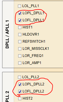
    I was able to view this video. By the end of the video when desired frequency is reached, do status register readbacks show DPLL lock? In your .tcs file that you sent I see LOFL and LOPL are still flagged but I'm not sure if that was read, updated and saved at the correct time. 

    Also can we monitor DPLL ndiv and rdiv paths on the status during this time? They should be shifting around and eventually slowly getting aligned until DPLL lock is reached. You have one of the them mapped in the .tcs file below you'll find the image for both. Connect to a scope and monitor during locking (I assume video above is coming out of releasing PDN or just programmed EEPROM and power up power down?)

    The over lock time isn't a surprise, 1 pps does take time to lock. We should be able to mute the outputs until DPLL lock is reacked and that way the output clocks don't come out until after lock. I will give instructions once you answer on above 2 inquiries. 

    Thank and regards, Amin 

    1. Status signal to update - highlighted is what's changed 

    2. In this case probe stat0 and stat1 - you can also program GPIO5 and GPIO6 to this status signal if that's easier 

    3. Same 2 signals exist for DPLL2 

    Status readbacks show no DPLL lock but not sure if these were read and saved at the correct time..  

  • 2045.PCIE_CPRI_GPS.tcs

    Hi

    LOFL is clear after 3 minute but LOPL still flagged.

    Our board have led indicator for Stat0, Star1, GPIO5, GPIO6. As config above LED of stat0 and GPIO is aligned but stat0 and stat1 is 180 degree out of phase.

    After 20 Minute the LOPL still flagged 

  • Hello, 

    So update Stat0/Stat1 and GPIO0/GPIO1 to be Ndiv/Rdiv for DPLL1 and DPLL2. Like this: 

    Then if the signals are in phase or 180 phase shifted, the LEDs should turn on together or perfectly turn on at different times. 

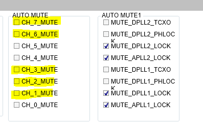
    Let's enable mute, and see if the output is indeed disabled while DPLL locks. I see in your updated .tcs, all these bits have been enabled, was this by accident or purpose? Was their anything different observed? Below is how I would enable them and see if there are any changes. 

    Thanks and regards, Amin

  • Hi

    I update the stat0/stat1 and GPIO5/GPIO6 as your comment then the Stat0 and GPIO5 are in phase, Stat1 and GPIO6 are in phase also 180 phase-shifted to Stat0 and GPIO5

    I tried the mute function as your comment but the output does not disable while DPLL locks

    I reduce the TCXO bandwidth and the frequency jump is reduced respectively. It seems the clamping frequency (during fast lock) depends on the TCXO bandwidth

    TCXO bandwidth           Frequency jump

    20Hz                               ~5kHz             

    40Hz                               ~10kHz

    200Hz                             ~500kHz

    1000Hz                           ~500kHz

    4000Hz                           ~500kHz                    

    Thanks

  • Is the TCXO being powered up at the same time that device is being powered up?

    How long before the TCXO reaches stability? 

    Regards, Amin 

  • Yes the OCXO is power up at the same time with the device. It take 30-60s to stability.

    Thanks