This thread has been locked.

If you have a related question, please click the "Ask a related question" button in the top right corner. The newly created question will be automatically linked to this question.

LMK05318: Zero-Delay Mode (ZDM) Synchronization for 1-PPS Input and Output

Part Number: LMK05318
Other Parts Discussed in Thread: LMK05028

Hi all

Would you mind if we ask LMK05318?

The datasheet shows "Zero-Delay Mode (ZDM) Synchronization for 1-PPS Input and Output" on P50.

<Question1>
Zero-delay mode synchronization is for OUTPUT7 only, isn't it?
Is it possible to use this function with other Outputs??

<Question2>
We would like to confirm the setting with LMK05318 on TICSPRO.
There are SYNC Phase Offset(s) and DPLL_REF_SYNC_PH_OFFSET.
What does SUNC Phase Offsets correspond for RXXX?  
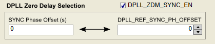

<Question3>
If DPLL_REF_SYNC_PH_OFFSET is 0 setting, will DPLL1(2) and OUTPUT7 be Zero-delay mode synchronization without phase offset?

<Question4>
There is the description Zero-Delay Mode (ZDM) Synchronization is for 1-PPS Input and Output.
So, in case of Input(Refrence clock) 148.5MHz, is it possible to use  ZDM function??

Kind regards,

Hirotaka Matsumoto

  • Hello Matsumoto-san,

    <Question 1>

    Zero Delay mode synchronisation is for OUT7 only. Other outputs will not have deterministic phase relation.

    <Question 4> 

    ZDM function is available for low frequency inputs. We cannot use ZDM for input frequency of 148.5MHz. I'd recommend to check if you could use SYNC functionality, which can synchronise one or more outputs with deterministic phase relation between outputs.

    For true zero delay mode operation, I'd also recommend LMK05028.

     <Question 3 & 2>

    DPLL_REF_SYNC_PH_OFFSET bits can be used to control the phase relation between Input and Output. Setting 0 would have no phase offset between input and output. Could you please explain a bit more on Question #2 for us to provide an answer?

    Thanks and Regards,

    Dinesh. 

  • Dinesh san

    Thank you so much for your reply!

    Could you please explain a bit more on Question #2 for us to provide an answer?
    ->We would like to confirm the diffrence between SYNC Phase Offset and DPLL_REF_SYNC_PH_OFFSET.
       As our assumption,
       SYNC Phase Offset : the delay time [XXns]
       DPLL_REF_SYNC_PH_OFFSET :  the value of register which corresponds for SYNC Phase Offset
       Is our recognition correct?

    And then,
    "ZDM function is available for low frequency inputs. We cannot use ZDM for input frequency of 148.5MHz."
    ->How much is the minimum low frequency inputs which ZDM function can use? 1MHz?

    Kind regards,

    Hirotaka Matsumoto

  • Hello Matsumoto-san,

    That description is correct.

    For ZDM mode, operation for 1 MHz input frequency should be okay.

    Regards,

    dinesh.

  • Dinesh san

    Thank you so much for your reply and your cooperation always!

    How much is the maximum reference frequency inputs which ZDM function can use?

    The datasheet shows there is the description for Hitless Switching with ZDM "Hitless Switching With 1-PPS Inputs Hitless switching between ...(typically 10 mHz for a 1-PPS input)."
    Actually, we would like to know how much reference frequency ZDM function can be used for.

    Kind regards,

    Hirotaka Matsumoto

  • Hello Matsumoto-san,

    For the maximum TDC rate of 26 MHz, I'd suggest input frequency less than 10 MHz for ZDM operation.

    Regards,

    dinesh.

  • Dinesh san

    Thank you so much for your reply.

    We would like to confirm one point finally.

    For the maximum TDC rate of 26 MHz, I'd suggest input frequency less than 10 MHz for ZDM operation.
    ->OK, we will inform our customer to use the maximum frequency TDM=10MHz.
       It seems that PRI and REF are divided 12 bit using ÷R(divider).  
       So, is it possible to use PRI=148.5MHz with R=15? -> TDM will be 9.9MHz.

    We appreciate your help always.

    Kind regards,

    Hirotaka Matsumoto

  • Dinesh san

    Thank you for your support always!
    Could you give us the reply for our last update?


    Kind regards,

    Hirotaka Matsumoto

  • Hello Matsumoto-san,

    Ideally, you could use the R-divider to divide the input frequency. However, since the reference R-divider is not synchronised, the purpose of zero delay mode would be lost. For example, When R-div is set to 15, for every 15 input clocks, 1 edge of reference clock would be generated. In zero-delay mode, it would be uncertain which of the 15 input cycle is the output locked to. Hence, the purpose of ZDM is defeated.

    I'd suggest setting R-div to 1 and apply < 10MHz reference clock at the input.

    Best regards,

    dinesh.