This thread has been locked.

If you have a related question, please click the "Ask a related question" button in the top right corner. The newly created question will be automatically linked to this question.

LMX2582: the chip's output was wrong & can't be locked, when I use external 20MHz clock signal from KEYSIGHT Waveform Generator.

Part Number: LMX2582

Hi, guys:

      I just meet a problem that my LMX-2582 can't be locked as I changed the fosc from cwx813-100MHz to the 20MHz, which come from external signal generator(KEYSIGHT 33500B Series waveform generator).

I was confused that my 100MHz reference works right , so did the 50MHz. I have checked several frequency outputs from 500MHz~2.5GHz, the lmx2582 can be locked .  

Why the external  20MHz clock signal can't work correctly?

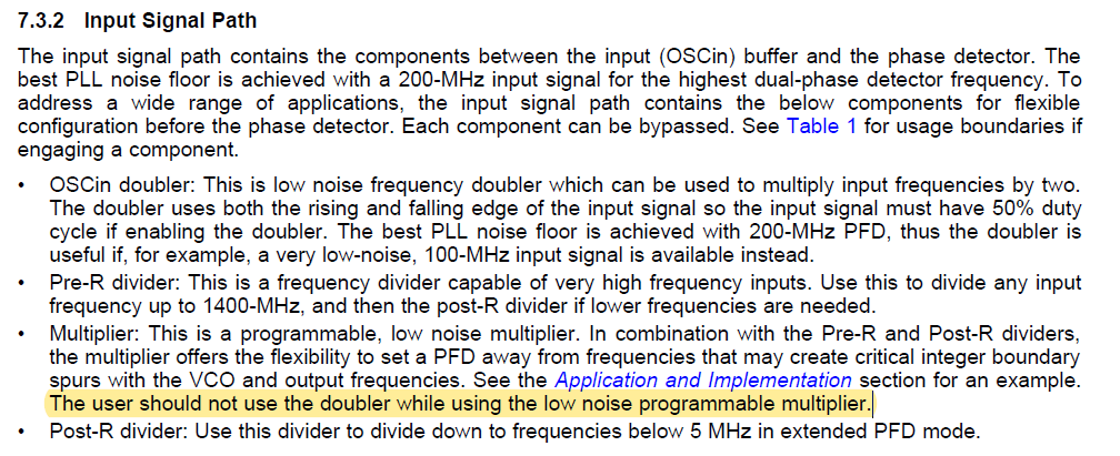
      what have I ignored? Cause I note that the input of the multiplier is 40MHz,which is almost the lower end, when 20MHz was used as fosc.     

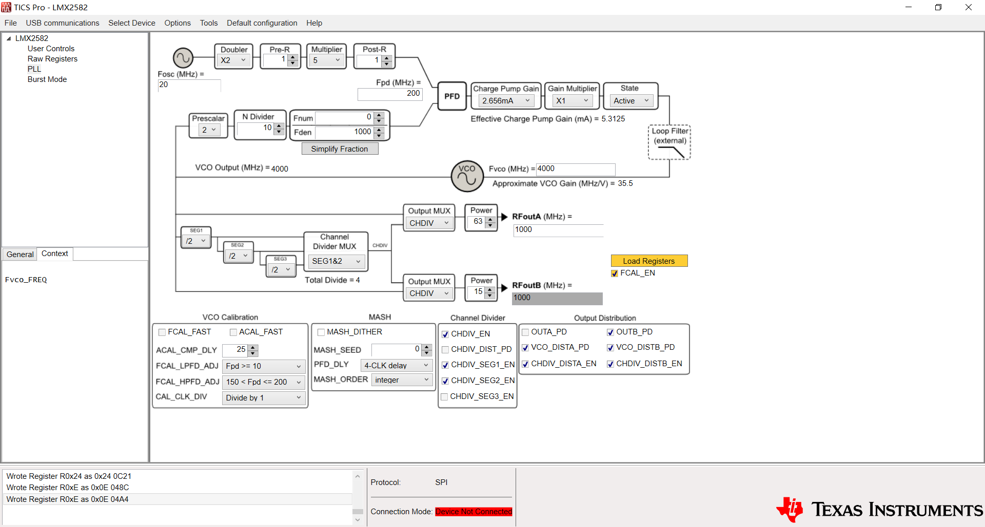
I have double checked the TISC Pro's  register configurations, there is no error report or warnings in highlight yellow or red. 

Is there anyone meet the same problem with me?

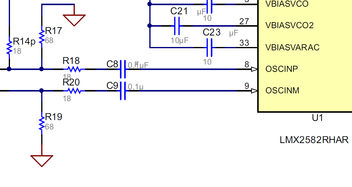
ps:   I layout my demo refer to the LMX2582 EVM (pretty close).

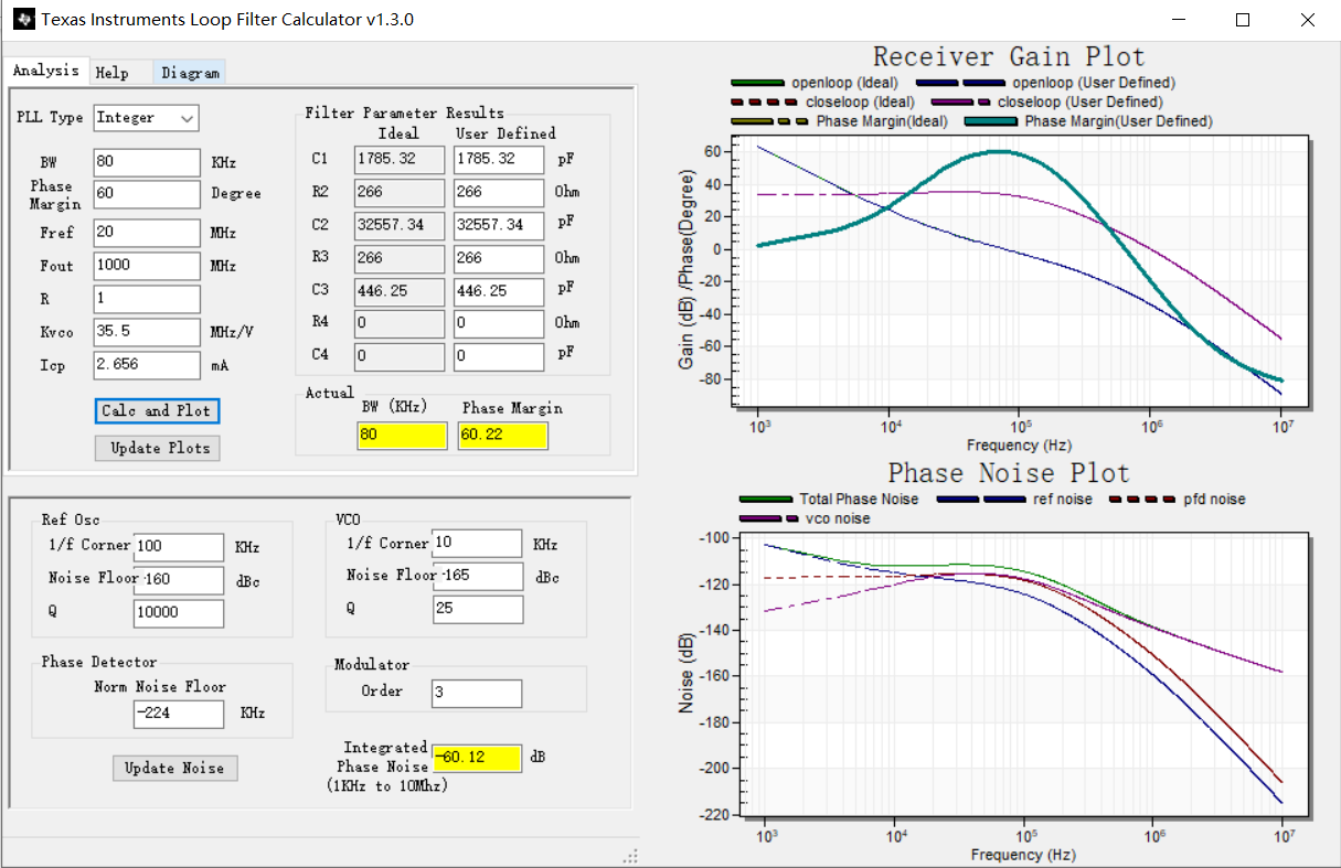
        I used the TICS Pro v1.7.0.0  to configure my lmx2582 & Texas Instruments Loop Filter Calculator v1.3.0. to change the loop filter parameters.

  • Hi Hua,

    Can you provide your TICS Pro .tcs file? 

    What is the format of the 20MHz clock signal? Square wave or sine wave? What is the amplitude?

  • Hi, Noel:

         I upload the screen shot of the TICS PRO.  & the Loop Filter Calculator. 

    I have to replace the capacitor C1 with 1nF,  C2 with 33pF,  C3 with 470pF in practice, & R2/R3 with 270Ohm.  Cause I couldn't find the devices with the thoretical values.

    what's the format of the 20MHz clock signal?

    I've try the square wave & sine wave both.The amplitude is 2Vpp(single-ended & single polarity, 0~2V) or 2VPP(single-ended & dual polarity,-1V~1V) .

    the voltage between R18 & C8 is about 1.5Vpp(0~1.5V or -750mV~750mV) , voltage on the pin OSCINP was shift to the Vcc/2.

    I also replaced the R14/R17/R18  with 33Ohm/51Ohm/33Ohm for the same reason as mentioned above.  

    I actually then reduced by half the clock signal. It doesn't work.

    But I found that the output frequency is about 1.2GHz, which is very close to the target 1GHz. the MUXout is in low level, while the Vtune is about 2.478V.

    Thanks.

  • Hi Hua,

    Please try again without the multiplier in the reference path. Either use x2 or Multiplier, cannot use both at a time. 

    In datasheet, section 7.3.2:

    "The user should not use the doubler while using the low noise programmable multiplier."

    BTW, please use PLL Sim to perform a more accurate simulation.

  • HI,Noel

         I  have reviewed the datasheet for the details. It did give a description of the OSCX2 & Multiplier. They can't be used at the same time.

    It seems that 40MHz is the lower limited value for the  LMX2582, I'll try to use the 40MHz as fosc later. 

    But I think maybe the TICS Pro could be updated,  to  indicate the user in highlight yellow/red when the OSCX2 & Multiplier were used together. 

    Thanks.