This thread has been locked.

If you have a related question, please click the "Ask a related question" button in the top right corner. The newly created question will be automatically linked to this question.

LMX2594: Glitchless, on-the-fly reconfiguration of N-divider

Part Number: LMX2594
Other Parts Discussed in Thread: LMK04208

I am currently planning a prototype design using the Xilinx ZCU111 board as a platform, which itself uses the LMX2594 to generate some of its clocks. My application requires that one of these clocks be periodically adjusted on-the-fly based on the result of a clock-error calculation, and this adjustment must be smooth - the clock may not shut down during the adjustment, and ideally there should be as little phase noise as possible during the transition from one frequency to the next.

The clock adjustments in question are expected to be quite small, and should be achievable using only the N-divider numerator value for control. I also see in the datasheet that the part provides a 'ramping' feature for smooth frequency transitions within a given calibration domain. However, using either the ramp, or a direct write to the numerator, seems to require writing to the R0 register (FACL_EN) and in section 7.3.4 I read, "To make the fractional spurs consistent, the modulator is reset any time that the R0 register is programmed." Does this mean that glitchless reconfiguration is simply not possible with this part? If it is possible, how would I best go about achieving it?

  • Hi Philip,

    Thanks for posting on E2E. I have assigned your post to the responsible engineer. He will respond to you early next week.

    Kind regards,
    Lane

  • Hi Phillip,

    How many frequency adjustment you need? As you pointed out, you may change the fractional numerator to "fine tune" the output frequency. If the change is small, a VCO calibration is not required. This method of fine adjusting the output frequency returns less or no glitch. However, care must be taken that spurs may become an issue to your system.

    Where is the reference clock came from? Adjust the reference clock frequency is the best way of tuning the VCO output frequency, especially when the adjustment is small. Let say you use a VCXO or VCTCXO as the reference clock, you could have a DAC in your system to provide on-the-fly tuning voltage to these XOs. The output frequency of the synthesizer will follow the reference clock frequency. There will be no additional glitch and spurs.

  • Hi Noel,

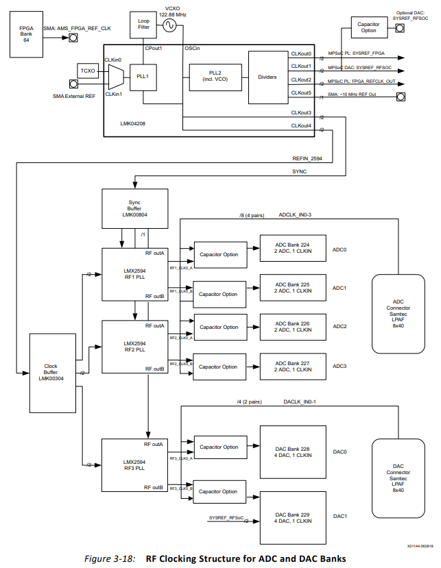
    Thanks for your reply. As I mentioned originally, the design in question is using a third-party evaluation board, so our control oversome parts of the design is limited. We know that it's possible to inject our own reference clock and tune that in order to achieve the desired result, but this means that our prototype requires an extra daughter card, with its own power supply and other accessories, and we'd prefer to avoid the extra time and expense if possible by tuning the clocks directly on the ZCU111 board itself. I've attached a page from the ZCU111 manual illustrating the clock structure:

    The clock most of interest to us is DAC0, at the bottom. It would be equally acceptable to modify DAC0 only (using the LMX2594) or all clocks at once (using the LMK04208). But we have no control over the TCXO frequency used as reference, or the 122.88MHz VCXO frequency in the loop filter of the LMK04208. The whole point of this inquiry is to avoid using our own SMA External Ref.

    With regards to 'how many' frequency adjustments are needed, I can't answer that in terms of an absolute number. This is a live clock-recovery system so we expect the clock will need to be periodically updated, on the order of once per second, based on measurements taken on an incoming channel. I don't expect most of these adjustments to be large; once the system is locked the first time we're probably looking at adjustments on the order of 1 kHz or less (probably much, much less). The main concern here is predictability - we have to be absolutely assured that these adjustments won't glitch the clock. 'Probably won't most of the time' isn't sufficient. I recall from the LMX datasheet that there are options available for manual 'calibration assistance' - provided that we can define a fixed range of frequencies that we will stay inside at all times, might this be a way to get the desired behaviour?

    I'd also like some clarification on section 7.3.4 of the LMX datasheet: "To make the fractional spurs consistent, the modulator is reset any time that the R0 register is programmed." From a plain reading, it sounds as though every time the PLL frequency is reprogrammed, the output will shut off (or otherwise be disrupted) for some period of time. This would be a complete nonstarter for us, so I need to have this bit explained in more detail.

    Thanks,

    Phillip

  • Hi Philip,

    Looks the only solution to you is to adjust the fractional numerator of RF3 PLL. In this case, you only need to program R43 and R42 in order to change the PLL_NUM value, you don't need a VCO calibration. 

    Every time we trigger a VCO calibration by writing R0, the loop will be broken (open loop) in order to perform VCO calibration. After calibration is done, the loop will be closed again and lock to the desired frequency. Obviously, there will be glitches whenever the loop is broken. Since in your application, you only need a few kHz of adjustment, VCO calibration is not necessary.