This thread has been locked.

If you have a related question, please click the "Ask a related question" button in the top right corner. The newly created question will be automatically linked to this question.

TPL5110-Q1: How to avoid forced DRIVE reset?

Part Number: TPL5110-Q1
Other Parts Discussed in Thread: TPS5110, TPL5110

Hi,

In our application we need MCU to sleep most of the times and take readings on defined intervals. TPS5110 with Delay time configured to around 60s does the job well. Mostly while taking reading MCU tasks completes withing 60s and we are good.

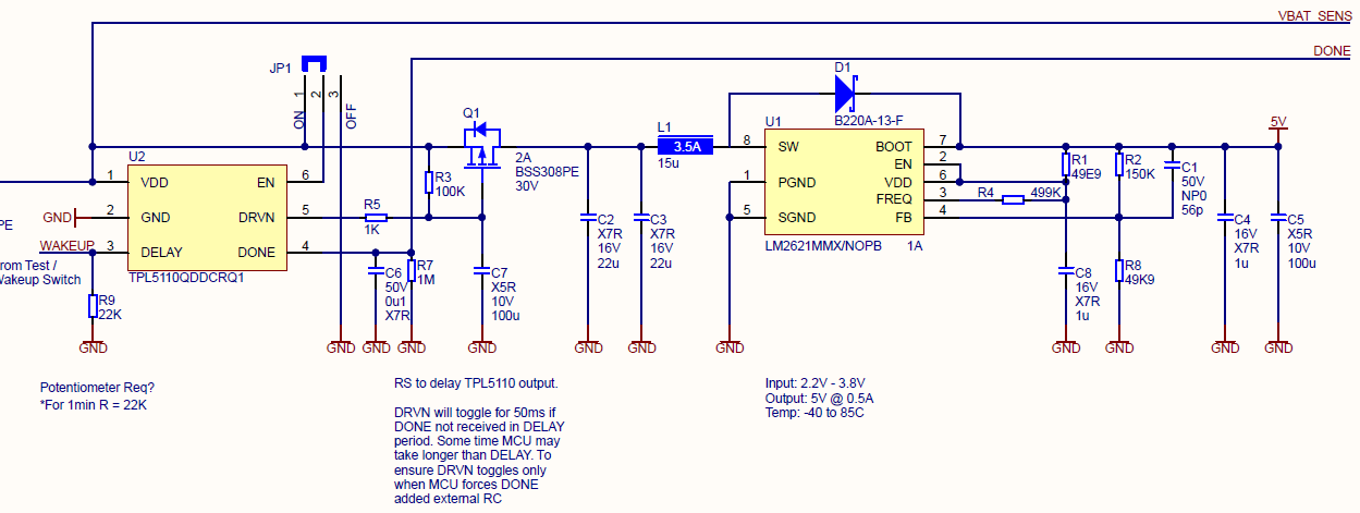
But these readings have to be transmitted over GPRS network once in a while. GPRS activity takes longer time and on expiry of DELAY time of 60s TPL5110 issues a 50ms pulse to DRIVE. This does a power cycle on MCU. We are looking for some way to avoid this pulse, unless a DONE flag is issue by MCU. We experimented by adding RC circuit on DRIVE pin to filter the pulse but it seems to work with eval board loosely wired with some external components, but doesn't work on the PCB we just got fabricated.

Please suggest what is the best way to handle this situation?

  • For this application, I think your approach is the best way to handle this; simply filter out a 50ms pulse. Try adjusting the values of the RC circuit on your PCB first. What are the R and C values?

    Kind regards,
    Lane

  • Hi Lane,


    Thanks for your reply. Please find the schematics below. We are using 1K and 100uf as RC. I understand 100uf is high, but we also tested with 100K and 1uf combination.

    Main issue we are facing is,  switching transients on DRV and DONE pins during the 50ms MOSFET reset.

    Yellow: DRV pin

    Cyan: DONE (Please observe the transients)

    Pink: M_DRV

    The amplitude of transients at DONE is around 3V and this leads to timer reset. Here it is important to note that with EVAL board we did not experience these transients.

    In terms of PCB layout, the Step-up converter input Caps are placed very close to 100uf RC. Track width used for RC on DRV pin is 8mil.


  • Thanks for sharing all of the information, I understand the problem now. I'm not exactly sure what is causing these transients. Perhaps it is coupling from a via or trace, if not some erroneous signal from the host.

    RC value on the DONE pin is 100ms; I would expect the transient to be filtered out more.

    Can you zoom in on the transients? you do do it on the same plot with DRV.

    Kind regards,
    Lane

  • It seems the issue was because of MOSFET leakage which was providing and alternate charging path for C7. Added a series 100K between Gate and C7 to increase charging delay. This seems to have resolve the issue.