This thread has been locked.

If you have a related question, please click the "Ask a related question" button in the top right corner. The newly created question will be automatically linked to this question.

LMX2594: mash_seed usage

Part Number: LMX2594
Other Parts Discussed in Thread: LMX2582

Hi all,

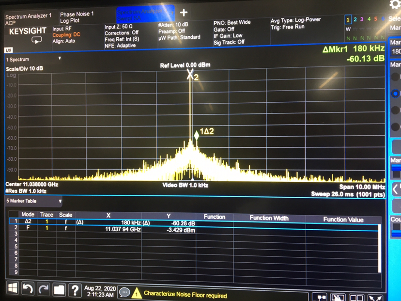
  I have found many fractional spurs in my new lmx2594 application on my board,mash order and PFD_DLY_SEL have set correctly.When i enable mash seed function R37[15] and set R40&R41,the spurs have optimized.But from the datasheet,there are considerations for mash seed to shift phase.For example,PLL_DEN>PLL_NUM+MASH_SEED.

In my aplliction,PLL_DEN=184320,PFD=184.32M,and the output of lmx2594 is 10G~12.5G,fractional mode.How do i ensure the above condition in so wide frequency band?

In addition, is there a trade-off between using this setting for other performance?

Thanks.

  • Hi There,

    MASHSEED can change the phase but it can also be used for noise optimization.

    PLLatinum Sim does model the impact of MASH_SEED on spurs, but not for a numerator of 0. The impact of MASH_SEED on spurs does not have a simple closed formula, but rather involves finding the sequence and calculating the Fourier Series as described in Dean's PLL book at https://www.ti.com.cn/cn/lit/ml/snaa106c/snaa106c.pdf

  • Hi Noel,

        I read the book but it is also have a simply comment on mash seed.

    if i want to set mash seed in Reg40&41,when i program this registers?I just set the value of R40&41 at the initial power-up sequence or after the sequence of changing frequencies each time?

    Thanks.

  • Hi There,

    After programming it to lock to a frequency channel, then program R37 to enable MASH SEED, then program R40 and R41 to adjust the SEED value. 

  • Hi Noel,

      I have another question:for the phase adjust,PLL_DEN>PLL_NUM+MASH_SEED must be satisfied.But my used frequency band is very wide(9.8~12.5G) and i have set PLL_DEN=184320 for 1k step.If PLL_DEN,PLL_NUM,MASH_SEED doesn't satisfied above condition,what will happen?Does it will worsen spurs or some other performance?

    Thanks.

  • Hi There,

    This requirement is for phase adjustment but not spurs optimization.

    I don't know how does the MASH_SEED setting affect spurs.

  • Hi Noel,

       I have also not used this function to optimize spurious before,but i have found some spurs when i debugged the lmx2594 output on our new board ,the oscin i have tested  there was no spurs in.And i have tried to adjust mash order and PFD_DLY_SEL according to the datasheet.Then i have read the datasheet carefully and found some description as follow:


    and i have tried set R37 and R40&R41,I found the spurs changed.But i am confused whether this setting will affect other performance or not with rarely description about this function on datasheet.

    Thanks.

  • Hi there, 

    the picture did not get through, would you please attach the picture again? (click the Insert/Edit Media icon)

  • Hi There,

    What is your OSCin freq and output freq? Which output frequency do you have spurs issue? 

    There are many different type of spurs, we have to use the correct method to strategically deal with them. MASHSEED does not work for all type of spurs.

    LMX2582 datasheet section 8.1.1 has a good description on spurs, please check ti out.

  • Hi Noel,

       My OSCin freq=368.64M,output freq is between 10Ghz and 12.5Ghz.

    Yes,there are many different types of spurs and different kinds of causes so we have to identity them and then minimize them.The spurs i met are sub-fractional.let me show you as follows,this is just one frequency :

  • Hi There,

    If your programmed VCO frequency is 10288MHz, I can see fractional spurs at multiple of 53.33kHz. You can try use 2nd order MASH, the spurs frequency will change to multiple of 80kHz. 

    To completely avoid this fractional spurs, use DEN = 18432001.

  • Hi Noel,

        Thank you very much for your reply and suggestion at first.But i can't change DEN to 18432001,because my channel step should meet the requirements of SCS (subcarrier spacing) =60Khz.

    So the frequency step of lmx2594 output which used as LO signal cannot be set at will.Besides, the VCO frequency at 10288.16M is just one frequency in my application,I need to be able to change frequencies freely in 10G ~12.5G. so if i use 2nd mash order which can improve the spurs at 10288.16M,but it doesn't apply to the entire band.In addition, the spurious needs to be optimized below - 70dbc at whole used band.

    Thank you very much.

  • Hi There,

    The amount of frequency change per step is not an issue with fractional PLL.

    If you set DEN = 184320001, given N(integer) = 55:

    With NUM = 150400001, we get 10288.000000184MHz.

    With NUM = 150460001, we get 10288.0600001837MHz. 

    We are changing the VCO frequency in 60kHz per step.

    If you set DEN to integer multiple of 184.32, you will get fractional spurs for sure.

  • Hi Noel,

       I have tried your advice to change DEN from 184320 to 184320001,there still some fractional spurs at VCO frequency such as 11038.16M,11538.16M. 

    Of course,i haven't test all the frequency of my used band.This spur is within LBW,do you have any other advice to suppress it below -70dBc  except change LBW more narrow.The configuration is the same as before,i just change N,DEN and NUN registers then set FCAL_EN=1 when i change frequencies.

     The data is as follow:

  • Hi There,

    What is the MASH_ORDER?

    Can you try different MASH_ORDER and adjust PFD_DLY_SEL to see if the spurs will go down?

  • Hi Noel,

      The default mash order in initial power up sequence is 4,and the PFD_DLY_SET is 3.

    Yes,i have tried to change mash order and pfd_dly_sel in different output frequency,the spur will go down 3~5dB.

    My loop filter is like this:c1=0.39n c2=100n,R2=0.068k ohm,c3=2.2n,R3=0.012k ohm,the LBW is around 300k in my used band.From your professional point of view, is there any problem with this loop design?

    Thanks.

  • Hi There,

    A wide loop bandwidth is desired for lower phase noise and jitter.

    However, all the fractional spurs, in this case, are multiple of 80kHz. That means the loop filter is not able to reduce their magnitude.

    If you can tolerate phase noise or jitter, you can reduce the loop bandwidth in order to reduce spurs.

    You may first try reducing charge pump current. In general, smaller current returns smaller spurs. In addition, without re-design the loop filter, a smaller charge pump current will reduce loop bandwidth, it should help reducing the spurs a bit.

  • Hi Noel, 

       Right,the original purpose of designing a wide loop bandwidth is to get optimal phase noise.

    I have tried to reduce  cp current  to 6mA(original is 12mA),the spurs at this frequency have lowered to an acceptable value.

    If i don't want to re-design the loop filter but with cp current changing to 6mA, is it any problem here?Such as instability of loop or something?

    Thanks.

  • hi there,

    Since the loop bandwidth and it characteristic depends on the charge pump current. In general, if you have design a loop filter with a certain loop bandwidth. when you reduce the charge pump current, the loop bandwidth will also reduce. Phase margin of the loop filter will also change.

    You can verify your loop filter with PLL Sim. Reduce the charge pump current and observe the change in loop bandwidth and phase margin. If the phase margin is greater than 30 deg, the filter is stable, although 30 deg phase margin will result in a peaking in phase noise at the loop bandwidth offset.

  • Hi Noel,

      Yes, I have verified the loop filter with PLL sim,it suggested me redesigning the filter from 10G~11.8G because the Loop Gain Change is larger than 40%,does it mean i'd better to redesign the loop filter for the cp current change?The phase margin is around 70 deg.

    Thanks.

  • Yes, better make the loop bandwidth variation as small as possible over the entire VCO frequency range.