This thread has been locked.

If you have a related question, please click the "Ask a related question" button in the top right corner. The newly created question will be automatically linked to this question.

Jitter (spurious) when using phase sync function

Part Number: LMX2572
Other Parts Discussed in Thread: TIDA-01410

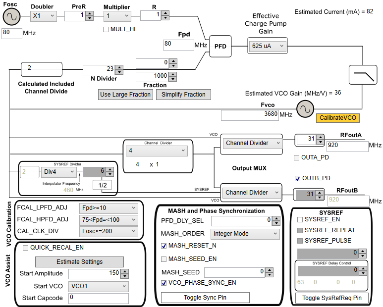
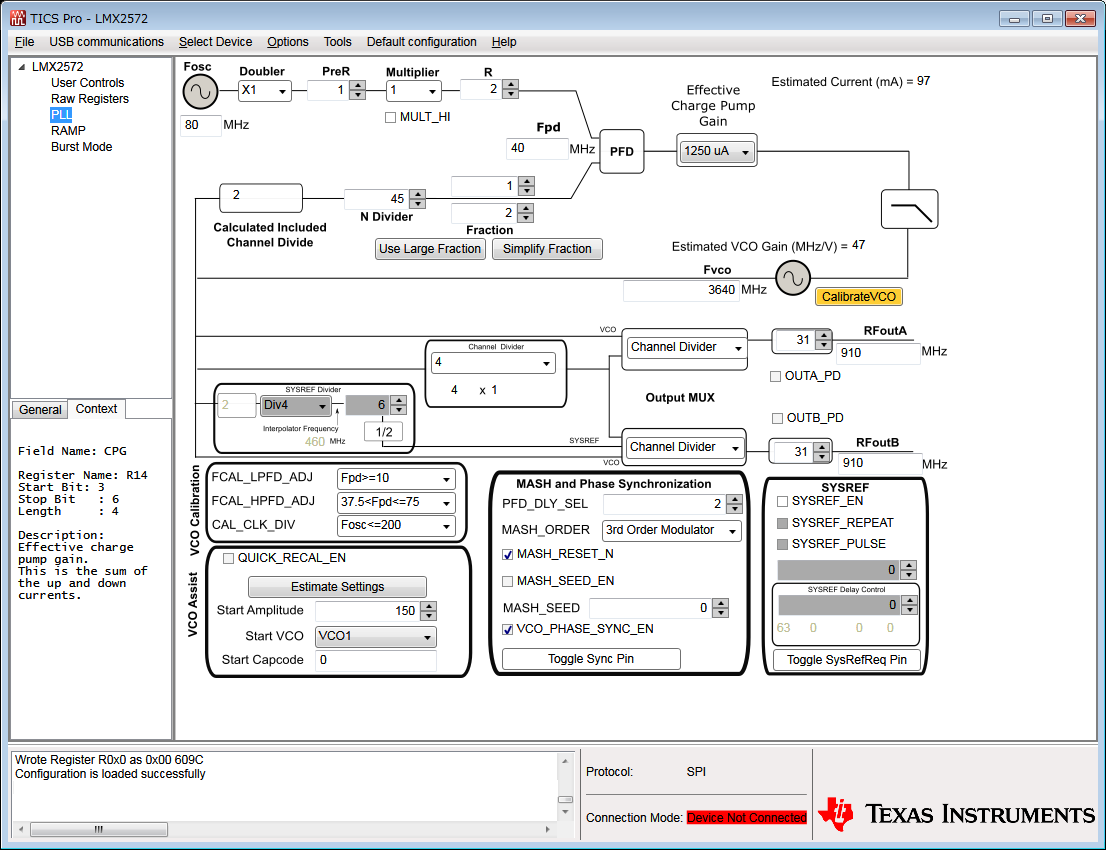
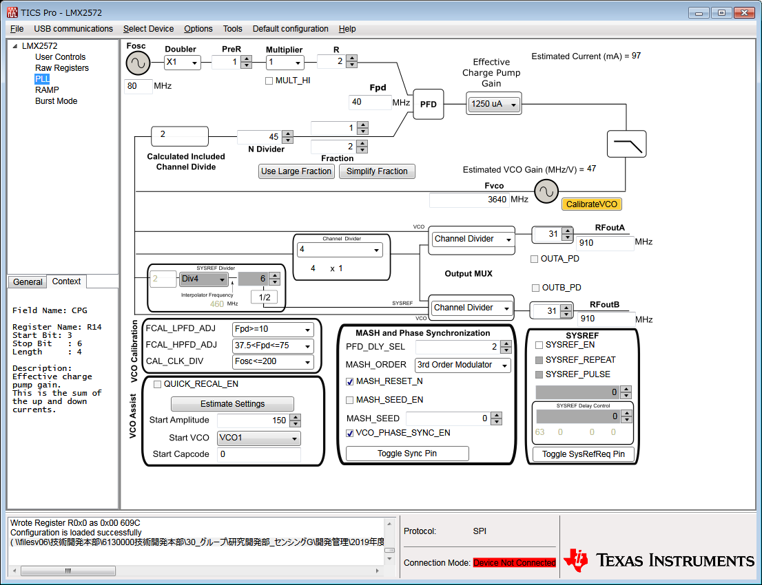
We are using two LMX2572s in integer division.
The conditions are classified as category 3 as follows.
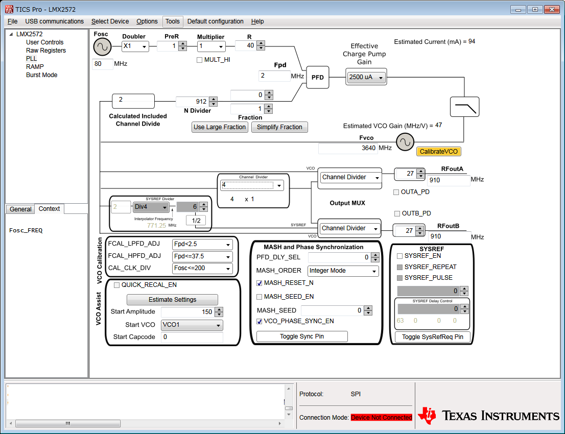
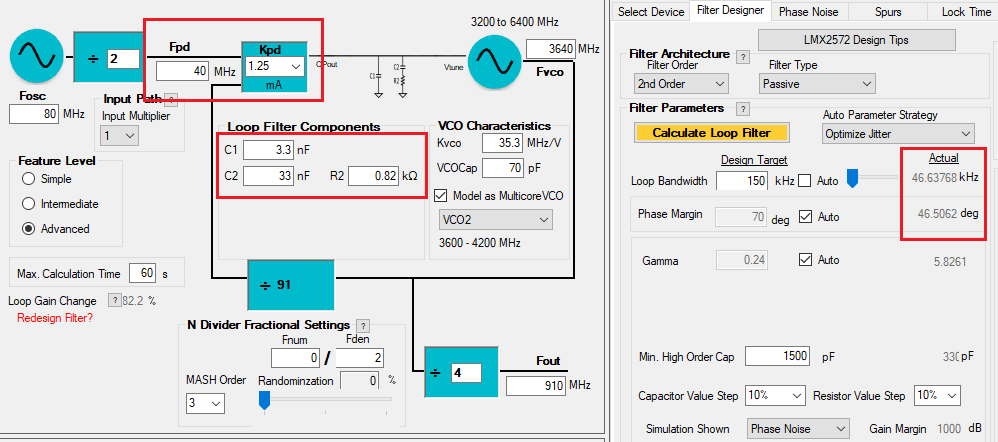
 CHDIV = 4, M = 1, fout/fosc = 910M/80M = 11.375
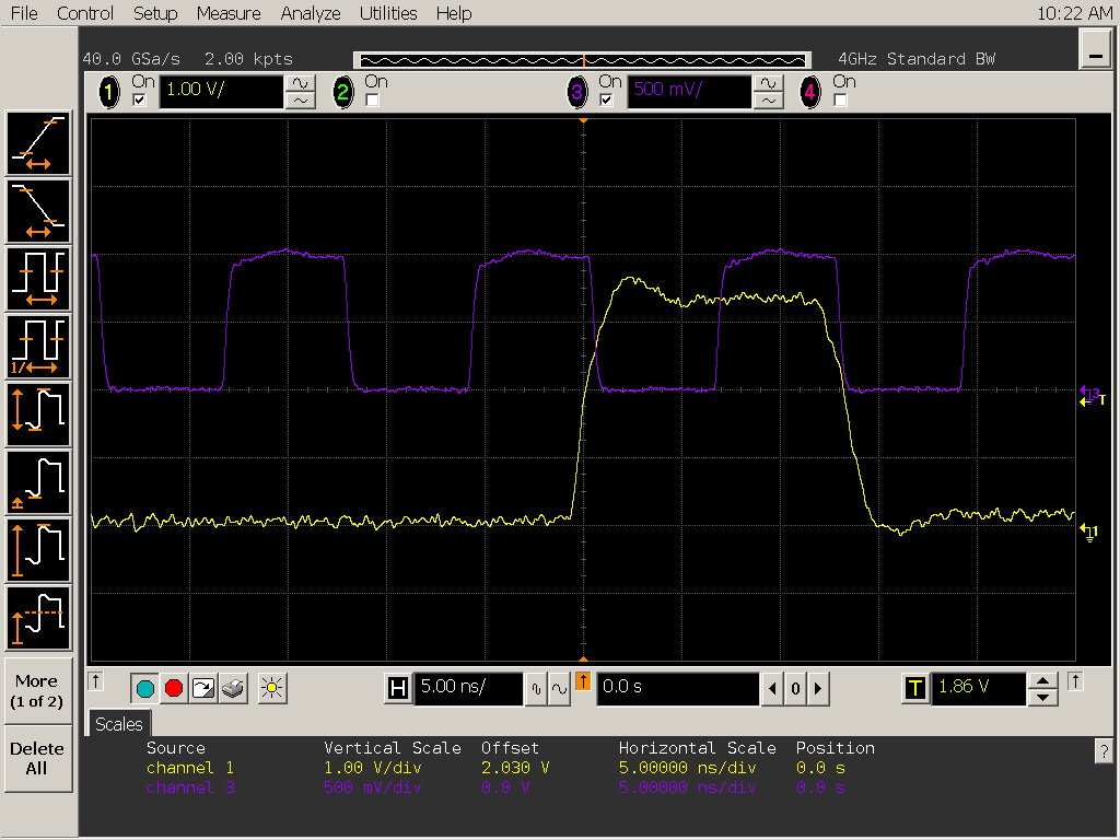
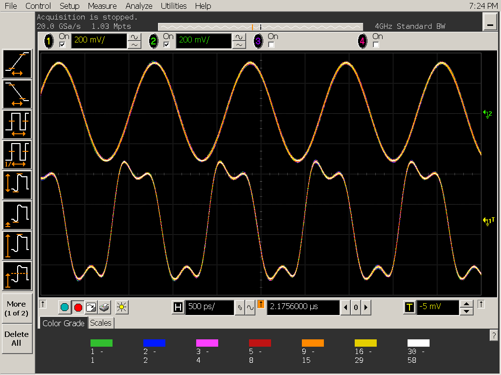
When the phase sync function was enabled and a rising edge was input to the SYNC terminal, jitter of about 150 to 200 ps occured on one of the LMX2572 outputs. When I observed this with a spectrum analyzer, I found a spurious 6.5 kHz offset.
Would you tell me the cause and solution?

From the reference TIDA-01410 and the demo movie, the "Timing Critical SYNC Example" is set to a fractional division setting. Do I have to set MASH_SEED and PLL_DEN and select other than Integer for MASH_ORDER as described in Document 2.2.2 Theory of Phase Shift even for integer division?

Thanking you in advance.


  • Hi,

    As 910 MHz is not a multiple of 80 MHz, this is indeed category 3 SYNC as you say.

    As this above example is in integer mode (MASH_ORDER=0), there should be no fractional spurs.  There are no state machines or frequencies on this chip running at that low of a frequency.

    So therefore, I am pretty sure that the 6.5 kHz spur is not coming just from the LMX2572.  For instance, it could be related to power supply.

    Spur debugging usually involves trial and error.  You should first power down the PLL in software and see if the spur goes away.  If it does not, then it is not related to the LMX2572.  If it does go away, it is likely 6.5 kHz spur energy coming onto one of the power supply pins.

    Now if you want to control the phase shift with MASH_SEED, you do need to change MASH_ORDER to nonzero number.  I recommend 2.   In this case, when you apply a non-zero MASH_SEED, it can impact the spurs.  But this is not the case you show abnove.

    Regards,
    Dean

  • I appreciate for your quick response.
    You mentioned that the power supply system is suspicious, but the spur did not occur before the SYNC trigger input, and even after the SYNC trigger input, it did not occur under the condition that output frequency/input frequency = integer.
    Could you confirm detail settings?

    The SYNC trigger is input at the CMOS level from our own FPGA.
    For the reason of the FPGA side, multiple pulses were input (the logic goes low after the completion of input), but is there a problem with this?

    I guess from the setting of Register R58 Bit 15 (INPIN_IGNORE), but is it bad if noise is superimposed on the SYNC pin?

    Regards,

  • Hi There,

    The 6.5kHz spurs should not be related to the register setting and in fact, your setting is basically correct except for the INPIN_IGNORE bit, it should be set to 0 in order to accept a SYNC pulse at the SYNC pin.

    So the spurs appear only after you have provide a SYNC pulse? How big is the spurs in dBm?

  • Spurious and jitter are no longer generated. However, there is no repeatability in the phase difference between the two LMX2572 outputs.
    I am inputting SYNC with the two outputs displayed on the oscilloscope, but rarely the phase may be off by ±90° or 180°.

    The phase shift seems to occur more easily as time passes after starting up the LMX2572. I'm concerned about the heat generation of the board, is this related to this?

  • Hi There,

    This is a Cat 3 SYNC, there is a timing requirement to the SYNC pulse. Did your SYNC pulse meet this requirement as shown in Figure 2 of the datasheet?

  • Following are the reference input fosc and SYNC trigger.
    SYNC trigger is matched to the falling edge of fosc (=80MHz). Therefore, the requirements are met with a setup time of ≈6.25ns ≥ 2.5ns and a hold time = 6.25ns ≥ 2ns.

  • Hi There,

    Not sure but can you try with a higher fpd frequency?

    Here is the .tcs file for the above configuration.

    6253.2572.tcs

    In addition, do you have a board similar to the TIDA-01410 or you were hooking up several individual boards together? Once awhile in the my lab, I was not able to make two boards in sync because of poor wiring between boards. After improving the wiring, I could get the boards in sync. 

  • I measured 60 inputs of SYNC in the tcs file you gave me and the phase of the two outputs did not shift.

    I'm using my own board with two of them on one board.
    The reason two waveforms are different is because only one of them has an LPF, and the reason phase is slightly offset is because the line length is not the same, so don't care about it.

    What is the difference in Fpd?
    What do I need to pay attention to in order to make it sync reliably with the original dimensions (Fpd=2MHz)?

  • Hi There,

    I will have to check with the team, we seldom operate this device at 2MHz fpd.

  • Hi There,

    There is one register I have missed to mention, R69, MASH_RST_COUNT. You may need to increase its value when fpd is just 2MHz (what is the loop bandwidth?)

  • Thank you for your suggestion, I increased the MASH_RST_COUNT to 1,000,000. However, two LMX2572s phase difference after SYNC trigger still rarely shifts by 90°.

    The lock-up time between Fpd=2MHz and Fpd=80MHz is almost same as shown below.

    Fpd=2MHz

      The design value of Kpd is 6.875mA. The TICS Pro image I first posted was a misconfiguration (causing the 6.5kHz offset spurious).

    Fpd=80MHz

  • Hi There, 

    With fpd = 80MHz and output = 910MHz, it is a fractional channel, make sure the MASH_ORDER is not set to Integer mode.

    In addition, when Phase Sync is enabled, the N-divider becomes 22 which is not a valid value when MASH_ORDER > 0x0. 

    With output = 910MHz, set fpd = 40MHz; MASH_ORDER = 3rd order. Suggest set charge pump current to 1.25mA. 

  • If fout = 910MHz, fpd = 40MHz, MASH_ORDER = 3rd order, charge pump current=1.25mA, it seems that I can confirm the operation with the RC value of the current loop filter. I can't do it immediately, but I will try it when the measurement system is free.
    However, if I design optimally with fpd = 40MHz and MASH_ORDER = 3rd order, will the loop filter become 4th order? In that case, the PC board would need to be redesigned, which would have a big impact for us. Fractional spurious is also a concern for me, because We can't calculate the level at Sync with PLLatinum SIM now.


    Would it be difficult to solve this problem with the original principle of fpd=2MHz, Integer?

    Thank you for your help.

  • Hi There,

    MASH_ORDER is a software configuration, it cannot affect the pole of the loop filter, which is a hardware implementation.

    With your loop filter, put fpd = 40MHz and charge pump to 1.25mA, the loop filter is still looking good. If this configuration solves your synchronization problem, you can keep this filter.

  • With the current loop filter, I tried the recommended settings.
    Output = 910MHz, fpd = 40MHz, MASH_ORDER = 3rd order, charge pump current = 1.25mA, Fraction=1/2.
    With multiple SYNC triggers, the output phase difference between two LMX2572s took two different values (0° or 180°).
    Only when I changed the output to 920 MHz and made it an integer division did the two phases match. What is the problem?

  • Hi There,

    I don't know why the phase is either 0 or 180 deg.

    I got informed by our FAE that you want to keep fpd=2MHz so that you can change the output frequency in 1MHz step.

    Please try this, the loop filter has been optimized for min. lock time.

    2572_1.tcs

    https://e2e.ti.com/cfs-file/__key/communityserver-discussions-components-files/48/2572_5F00_sim1.sim

  • I tried the attached setup.
    I input the SYNC triggers at an interval of about 1 second, and the output phase difference between the two LMX2572s took four different values in 90° steps.
    When the output frequency was doubled to 1820MHz, the output phase difference became two different values in 180° steps, and when it was quadrupled to 3640MHz, output frequency = VCO frequency, the phase difference was fixed.
    I think it can be explained by thinking that Channel Divider is not included, but is there any possible cause such as register setting or board layout?

  • Hi There,

    I cannot make a guess what would that be happen unless I setup a bench to verify. Unfortunately I don't have lab access at the moment due to COVID. 

    I see our FAE is following this case with you, let's continuous offline.