This thread has been locked.

If you have a related question, please click the "Ask a related question" button in the top right corner. The newly created question will be automatically linked to this question.

LMH1983: CLK out1 27MHz question

Part Number: LMH1983
Other Parts Discussed in Thread: LMH1981

Hi Team,

Would you advise below 4 questions from my customer?

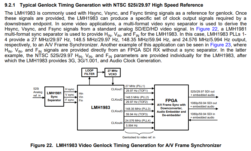
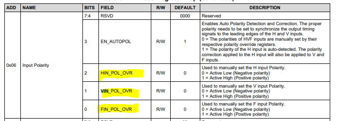
1, Is it possible to do Genlock by applying F sync(Fin) sync signal only?

2, CLK out1 is used for 27MHz normally, but can I output 27MHz - 1000ppm(=26.973MHz)?

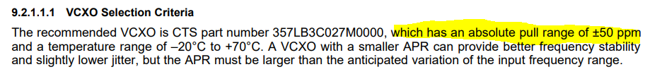
3, To what extent is the 27MHz VCXO XOin+ pin allowed to 27MHz±? Do you have specs?

4, If you have any know-how about how to use this IC (such as error behavior avoidance or

    special characteristics), we would appreciate it if you could give us information.

Thanks

Best regards,

Shidara

  • Hi Shidara-san, 

    Question 1, let me double check and get back to you. 

    Question 2, I don't believe so, but I will double check and get back to you. 

    With regards to question 3, review VCXO selection section on the datasheet: 

    question 4, is the IC being used on the EVM? if so the EVM user's guide is a good document to follow: https://www.ti.com/lit/ug/snlu001/snlu001.pdf?ts=1598849803722&ref_url=https%253A%252F%252Fwww.ti.com%252Fsitesearch%252Fdocs%252Funiversalsearch.tsp%253FsearchTerm%253Dlmh1983

    Thanks and regards,

    Amin

  • Hi Amin-san

    I'm Sohhei, who asked Shidara-san these question.

    Thank you for your quick response.

    Q.1, 2 : Thank you for confirming, Waiting for your reply.

    Q.3,: OK, I'll check the section.

    Q.4,:No, I dont use EVM. But I'll check this document.

    And I have additional questions for this IC. Would you advise below the questions?

    Q.5:Is it possible to do Genlock by applying a Clock the frequency of which is 10~100kHz Order to Hin Pin only?
          In the figure28 on the datasheet, written only 32, 44.1, 48 or 96 kHz (Audio), 27 MHz (Video),10 MHz (GPS).

    Q.6:Is it possible to do Genlock by applying H Sync to Hin Pin only?

    Q.7:Is it possible to do Genlock by applying F sync to Fin & H sync to Hin only?

    Thanks
    Best regards,
    Sohhei

  • Hi Sohhei, 

    I'll work on these questions and reply to you. It may take a few days. 

    Thanks and regards,

    Amin

  • Hi Sohhei-san, 

    Has the LMH1981 been considered? LMH1981 is a sync separator and can perfectly provide the signals needed by the LMH1983 in order to genlock. From the datasheet: 

    Thanks and regards,

    Amin

  • Hi, Amin-san

    Thank you for your replay.

    > Has the LMH1981 been considered?
    No, I have not, because of space factor. So, we'd like to know the other use case of LMH1983 in order to genlock.

    Please give me answer about Q1,2 and Q5~7.

    And also, I have additional questions for this IC. Would you advise below the questions?

    Q.8 I'd like to know Whether the input pulse (to Fin, Vin or Hin)  responds to rising edge or falling edge.
           In my understanding, it depends on 0x06 register (Input polarity) setting, "Active Low"-> "Falling Edge" and "Active High" -> "Rising Edge." 
           Is it correct?
    Q.9  In the figure28 on the datasheet, It is written only Hin. In this case, should I do about Fin and Vin.

    Thanks
    Best regards,
    Sohhei

  • Hi Sohhei-san, 

    No LMH1983 does not have capability to shift output by 1000 ppm. This is confirm. 

    Only Hin signal is needed to lock the PLL. Vin (and Fin for interlace video input) is only needed to align the output TOF pulses. 

    With regards to Hin frequency, for 10~100 kHz Auto Format Detection (AFD) logic needs to be disabled through register (EN_AFD bit =0). Secondly, PLL1 REF div and FB div need to be manually configured to obtain similar PLL1 PFD rates like shown for the auto-detected input formats listed in Table 2 (PLL1 PFD rates range from ~6kHz to 37 kHz). So for example: 

    • For 10 kHz Hin, program PLL1 REF div and FB div to 1 for PFD of 10 kHz 
    • For 100 kHz Hin, program PLL1 REF div to 1 and FB div to 10 for PFD rate of 10 kHz 

    Keeping PFD rates in this range allows the use of the same external PLL1 loop filter design to maintain similar PLL1 loop bw across the different input formats. 

    Default polarity is to lock to the falling edge, but it can be flipped to toggle to rising edge through register: 

    Thanks and regards,

    Amin

  • Hi, Amin-san

    Thank you for your replay and please excuse my late reply.

    >Only Hin signal is needed to lock the PLL. Vin (and Fin for interlace video input) is only needed to align the output TOF pulses.
    I understand It is answer for Q.1, 2, 5, 6, 7.

    >Default polarity is to lock to the falling edge, but it can be flipped to toggle to rising edge through register: 
    I understand It is answer for Q8.

    Please give me answer about Q9.

    And also, I have additional questions for this IC. Would you advise below the questions?

    Q.10 I'd like to output TOF1/2/3 25Hz (PAL) in free-run mode. How to set this IC?

    Q.11 In the case of Q.10, are all TOF signal in phase?

    Thanks
    Best regards,
    Sohhei

  • Hi Sohhei-san, 

    If Fin and Vin are not used you should be able to leave them floating. 

    Please review table 2 with regards to getting TOF at 25 Hz - PAL format is specified in there. 

    Regards,

    Amin

  • Hi, Amin-san

    Thank you for your replay.

    > If Fin and Vin are not used you should be able to leave them floating. 
    I understand It is answer for Q9.

    >>Q.10 I'd like to output TOF1/2/3 25Hz (PAL) in free-run mode. How to set this IC?
    > Please review table 2 with regards to getting TOF at 25 Hz - PAL format is specified in there. 
    I check table 2 and try to change Feedback Divider Parameter Value(Register Name:DIV_N1 ADD:0x2B[6:0],0x2C[7:0])
    from default value to 1728(refer to table 2). But this register cannot be changed and it returns to the default value(1716).
    And also I change the below registers from default value.
    - [Register Name](Address):[Setting Value]
    - FOUT_HIZ_FOUT1(0x0A[0]) : 0 
    - FOUT_HIZ_FOUT2(0x0A[1]) : 0
    - FOUT_HIZ_FOUT3(0x0A[2]) : 0
    - EN_AFD(0x05[5]) : 0 
    - PLL1_MODE(0x05[4:3]) : 0
    How to set this IC?
    Please let me know register setting concretely. (Register Name & Setting Value).

    And, Please give me answer about Q11.

    Thanks
    Best regards,
    Sohhei

  • Hello, 

    Auto Format Detection needs to be disabled, otherwise the register is read only. 

    Thanks and regards,

    Amin 

  • Hi, Amin-san

    >Auto Format Detection needs to be disabled, otherwise the register is read only. 
    Yes, I know, so I change EN_AFD(0x05[5]) register to 0. 
    Please let me know register setting concretely. (Register Name & Setting Value).


    And, Please give me answer about Q11.
    (Q.11 In the case of Q.10, are all TOF signal in phase?)

    Thanks
    Best regards,
    Sohhei

  • hmm my understanding is when AFD is disabled that should allow it to happen... I will have to look further into this, it will take some time. 

    Amin 

  • Hi Sohhei, 

    Re-looking this over, it seems like these updates never happened: 

    (from the datasheet)

    8.4.2 User Defined Formats

    There are several registers in the LMH1983 that are loaded automatically based on the format of the reference that is detected. The LMH1983 allows the user to define a non-standard format and a corresponding set of values to load into the appropriate registers if that format is detected. In order to identify the format, the LMH1983 measures the frequency of the Hsync input, counts the number of lines per frame in the format, and detects if the particular format is interlaced or progressive. The Hsync frequency is measured by counting the number of 27 MHz clock edges that occur in a period of time equal to 20 horizontal sync times. To implement a user defined format, the following registers are configured:

    • The minimum and maximum permissible count must be set, thereby establishing a window of frequency for Hsync. Registers 0x51 and 0x52 define the 16-bit value for the low end of the frequency range, while Registers 0x53 and 0x54 define the high end of the frequency range.

    • Registers 0x5A and 0x5B define the number of lines per frame for the format.

    • Register 0x5D, Bit 4 indicates whether the user defined format is interlaced or not.

    • Register 0x5D, Bit 7 enables the detection of a user-defined format.

    • Once the user-defined format is detected, the contents of Registers 0x55 through 0x59 configure PLL1 to lock to 27MHz, which is then used as the reference for PLL2, PLL3, and PLL4. Table 2 lists the supported standard timing formats.

    Table 2 includes the relevant parameters used to configure the LMH1983 for the input and output formats. Auto-detection of the input is supported for the formats listed in Table 2. The input format can also be programmed manually by the host via I 2C if it is necessary to override the auto-detection feature.

    I didn't see any updates mentioned to registers 51 - 54. This is needed. 

    Thanks and regards,

    Amin 

  • Hi, Amin-san

    Thank you for replay.

    > Re-looking this over, it seems like these updates never happened: 
    Ok, I'll check registers 51 - 54 and try again.

    And, How about Q11? 
    I write my question again with a supplement, 
    "Is it a specification that all TOF signals are output in phase in free run mode? "

    Thanks
    Best regards,
    Sohhei

  • Hi Sohhei, 

    Why wouldn't they be phase aligned? 

    I think it would be best to confirm on your setup but not sure why this keeps coming up. 

    Amin 

  • Hi, Amin-san

    > I think it would be best to confirm on your setup but not sure why this keeps coming up.
    According to 8.3.11 10 TOF1 Alignment and 8.3.11 TOF2 and TOF3 Alignment, 

    there are four different alignment modes.

    TOF ALIGNMENT MODE:
    1. 11'b (default): PLL1 never attempts to align.
    2. 10'b: PLL1 always forces alignment to FIN.
    3. 00'b: Automatically force alignment to FIN when they are misaligned.

    It depends on Fin, but in free run mode, FIN is not used.
    So, I'd like to know the specifications about TOF signals in free run mode.

    Thanks
    Best regards,
    Sohhei

  • Hi Sohhei-san, 

    Apologies, I had confused this thread discussion with something else.. 

    In HIN-only mode (no V/F IN reference), TOF signals can output at the configured frame rate, but there would be no input frame reference to align with.  So TOF alignment means nothing without reference H/V (progressive input timing) or H/V/F (interlaced input timing).

    Thanks and regards,

    Amin 

  • Hi, Amin-san

    > Apologies, I had confused this thread discussion with something else.. 
    Please don’t worry about it. 

    > In HIN-only mode (no V/F IN reference), TOF signals can output at the configured frame rate, but there would be no input frame reference to align with.  So TOF alignment means nothing without reference H/V (progressive input timing) or H/V/F (interlaced input timing).
    Let me make sure I understand you correctly. You mean in HIN-only mode (no V/F IN reference), if we change TOF alignment mode setting(0x11~0x13), nothing happens.

    And also, I have additional questions for this IC. Would you advise below the questions?

    Q.12, According to 8.3.11 TOF2 and TOF3 Alignment, TOF2 and TOF3 are generally aligned with TOF1.
    In HIN-only mode (no V/F IN reference), are TOF2 and TOF3 aligned with TOF1 ?

    Q.13, When H/V/F IN reference input and sets PLL1 operating mode(0x05[4:3]) to Force Free-run,
    are TOF signals aligned with H/V/F IN reference input ? 

    Thanks
    Best regards,
    Sohhei

  • Hi Sohhei-san, 

    Yes, that is my understanding. Without a V/F reference changing the TOF alignment mode setting is irrelevant. There's nothing TOF will be trying to aligned to. 

    Q12. TOF2/TOF3 might or might not be aligned with TOF1. And there might be random phase jumps. What purpose does the TOF signal serve if there are no V/F references? 

    Q13. In force Free-run. HVF inputs will be ignored. The device is forced into free-run operation. So essentially there are no H/V/F from device's view point. 

    Please start a new thread for more questions. It's okay to come back to a thread once if there are more questions along the same line or an answer leads to another question, but this particular thread is approaching 2 months. 

    Thanks and regards,

    Amin