This thread has been locked.

If you have a related question, please click the "Ask a related question" button in the top right corner. The newly created question will be automatically linked to this question.

LMK04832: LMK04832 enable doubler at PLL2 unable to lock the circuit

Part Number: LMK04832

Hi,

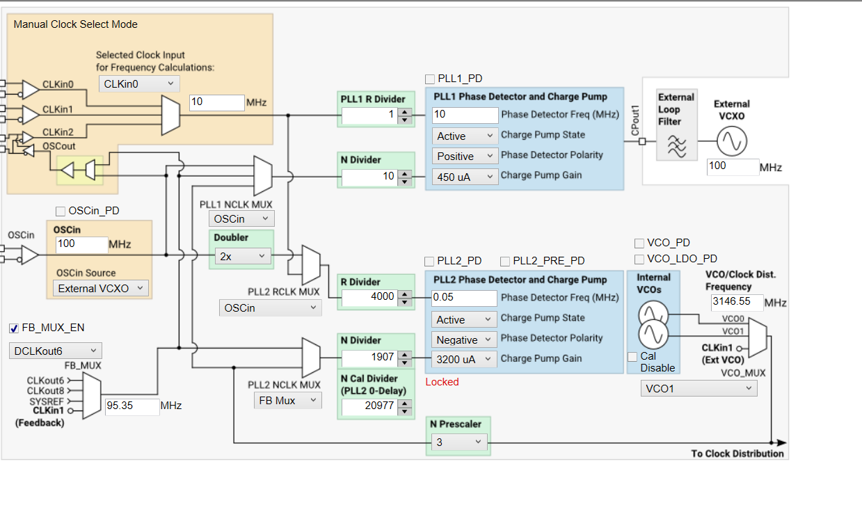
I faced a problem in locking PLL2 when I enabled the doubler. The configuration is shown as below:

From the datasheet, I saw that enable double can get better phase noise result and in some of the previous design that use LMK04832 had also enable the doubler but didnt not face any issue. But for my case, when i enabled the doubler, the PLL2 unable to lock. If i disable the doubler and change the R2 divider into 2000, the system able to lock. This sounds weird to me as i thought enable double can reduce the phase detector frequency and hence should able to lock easily than that without doubler.

I also attached the image for PLL2 loop filter parameters, from PLL Platinum the phase margin looks good and jitter also very small. I doenst sure what cause the PLL2 unable to lock in this case. Besides that, I wondering how to use the input mutiplier in PLL Platinum Sim, I initially thought it is refer to the doubler, but it seems it is not. Can explain more to me how to use this input multiplier as well? Thanks.

  • Hello Ee,

    In the current configuration posted, the device should be locked when:

    FB_MUX output / N-div = OSCin x 2 / R-div

    You are meeting the condition in the screenshot sent over. Additionally the main advantage of using the doubler in better phase noise should be from the higher phase detector frequency. In this case since you are using the doubler and increasing the divider 2000->4000, you are negating this effect. Please compare the simulation you posted above with a simulation of the doubler enabled with divider 4000.

    Since the PLL is setup in cascaded 0-delay mode (fixed deterministic phase relationship of the phase of the PLL2 input clock (OSCin) to the phase of a clock selected by the feedback mux) I believe the issue may be with the PLL2_N_CAL[17:0] value programmed.

    The VCO frequency / (pre-scaler x PLL2_N_CAL) must be equal to the phase detector frequency. This condition is also true in the above configuration.

    I will need to try this configuration on my EVM and get back to you later this week. Please let me know if there is any update with the debug.

    What version of TICSPro are you currently using?

    Thanks,

    Vibhu

  • Hi Vibhu,

    How can I compare the simulation using PLLatinum Sim with double enabled as i noticed the input multiplier is not functioning(maybe I do not know how it work for this input multiplier). I got try to change the input =200MHz instead of 100MHz and R=4000 instead of 2000 to simulate the case of doubler enable, but doenst seem any changes in the result. Maybe you can show me how to configure with enable doubler in PLLatinum simulation tool in this case. Thanks

  • I miss out your question on the simulation tool version i used.
    for TICS pro: TICS Pro Install, Ver 1.6.9, 2018-12-11 version

    for PLLatinum Sim: Setup_PLLatinumSim-1.5.3.0 version

  • Hi Vibhu,

    Ee Wen has transitioned and I am taking up this issue. I am suspecting the VCO itself or the control voltage has gone to the supply rail. I am measuring the DCLK8 as my main output with a divider value of 11. (as what the screenshot by Ee Wen is showing). I measured 286.05MHz at the output when the doubler is off (R_divider is 2000). When the doubler is on (R divider is 4000), the main output becomes 310.05MHz instead. Phase noise increased a lot so I suspect the PLL is not working as expected even though the output seems stable with a spectrum analyzer. 

    If we back-calculate the VCO frequency, it is 310.05*11=3410.55MHz, I am using VCO1, so the max tuning frequency is up to 3255MHz only, so it seems the VCO is already hitting its upper limit. 

    Do you have more findings from your end? Any setting could have caused this? The Charge Pump polarity? The gain? Or the sync across clocks?

    -Hao Jie

  • Hello Hao Jie,

    Can you send me your configuration file with the doubler enabled, so I can check / load it on my device?

    Yes, I agree with your back calculation. However if we enable doubler and use a double the R-divider the VCO frequency should not change.

    Thanks,

    Vibhu

  • I am using the config header file to generate the bin file, is the header file good enough for you? I've attached them here.
    Config with Doubler.h

    Config without Doubler.h

  • Hello Hao Jie,

    Thank you for these files. A TICSPro file would be easier but I can work with these. If possible after running your script can you open up the device on TICSPro and go to "File"->"Export hex register values"?

    Thanks,

    Vibhu

  • Hi Vibhu,

    Unfortunately right now I can't really access the register yet. I could only program the register right now. And I am not using the TICS software to program the chip in my appication

  • An update to this issue. I've measured the Charge Pump 2 output, in normal condition (doubler off), the voltage is around 1.51V. With the doubler on, the voltage goes to 3.28V, basically the power rail. 

    I guess the CP is trying to correct the frequency difference, as the internal VCO has a negative slope, so it tries to reduce the output frequency, but for some reason, the VCO does not respond. Looks like the CP is working okay, or at least the logic is. Do you have any guess why does the VCO not lower its output even if the CP has railed?

  • Hello Hao,

    Thank you for the update. I have converted the files you've sent over to a format I can load onto .tcs pro. Tomorrow I will test them to see if I have the same issue and debug from there.

    Thanks,

    Vibhu

  • Hello Hao,

    I took a look at this further, the PLL2 phase detector frequency you are using (50 kHz) is not a typical use case for this device, and isn't ideal for good phase noise performance. With the default loop filter on the EVM I couldn't get PLL2 to lock even with the doubler disabled and I am not surprised by this. The most probable reason for your observation is the possibility that your loop filter is unstable.

    To improve the phase noise performance of the PLL I recommend using a higher phase detector frequency. You will need to adjust the OSCin frequency or possibly the PLL2 VCO frequency to increase the phase detector frequency.

    Thanks,

    Vibhu

  • Hi Vibhu,

    I reworked the EVM with a 100MHz VCXO. I've loaded the same config as above, with some slight adjustment to the clock output (I've changed the of of the divider to 1 for easier debug), and the result is the same as my board. So PPL2 still does not lock, and the Vtune_PLL2 is showing 3.3V. I've noticed sometimes it will show 0V as well. Here is the TICSPro file for your reference:/cfs-file/__key/communityserver-discussions-components-files/48/10MHz-Large-N-and-R.tcs

  • Sorry I have overlooked this before the reply. Could I trust the filter design on PLLatinum Sim? As Ee Wen pointed out before, the software shows our filter is stable. 

    Regarding the Phase Detector frequency, unfortunately, I can't really change it as I need the resolution. I could accept a degradation on the phase noise performance but if the loop would not even lock this is a problem. In the datasheet there is no Min Freq specified for Phase Detector frequency, any other way I could make this work?

  • Hello Hao,

    Yes the filter designer is accurate for typical conditions as this is a simulation tool. The farther you go from a common use case the less accurate the simulation will be. In your case the extremely low phase detector might not give you a perfect simulation.

    I understand that a higher phase detector frequency is not acceptable in your design. However, I would experiment with a higher phase detector frequency to get the park locking. If this locks but your setup doesn't then unfortunately, there's not much we can do except maybe trying different loop filters. This may include increasing the phase margin for more stability. If increasing the phase detector frequency does not help it could be related to the loop filter.

    Thanks,

    Vibhu

  • Hi Vibhu,

    I've tried to increase the Phase Detector frequency. Around 300kHz, it locks, but only while the doubler is turned off. This is very similar to the observation on the actual board. Can you provide some insight into this as from the datasheet, it seems enabling the doubler is the recommended way to go, but I am failing to lock after enabling it. I would need a strong reason to turn this off because from the high level diagram it seems like a small difference.

  • Hao,

    I replicated your setup in the lab with a 100MHz Wenzel OCXO as the OSCin input, same loop filter, PFD, etc (though I did change the VCO frequency to 3200MHz, to make testing N-divider values easier - in practice this does not affect my findings). Indeed, the PLL could not lock with large R and N divides. And upon increasing the phase detector frequency I could get the PLL to lock.

    I locked the PLL with 1MHz phase detector frequency, set PLL2_FCAL_DIS=1 (box below internal VCOs that says "Cal Disable"), and changed the R and N divides to set the phase detector frequency to 0.05MHz, and I achieved stable lock. It seems that, with such a low loop bandwidth and phase detector frequency, the VCO calibration is taking too long and failing.

    The VCO calibration process is used to calibrate out variations in VCO frequency vs control voltage over temperature, and should be run at the frequency of operation. Normally the VCO calibration is triggered by writing the LSBs of the N-divider, but by setting PLL2_FCAL_DIS=1 you can bypass the calibration. Because your specified VCO frequency is already at GCD frequency with the 100MHz reference using PFD=0.05MHz, and you can't get the PLL to lock, it seems you can't calibrate at the frequency of operation. However, you could pick a very close value, e.g. 3146.5MHz (GCD 0.5MHz) at which the PLL will lock, use this frequency to establish the VCO calibration with different R and N divides, set PLL2_FCAL_DIS=1, and change the R and N dividers back to allow the specific operating frequency you need. Because the calibration is slightly off from the frequency of operation, the operating temperature range over which the calibration is effective will be reduced - the reduction in calibrated operating temperature range will be proportional to the offset of the calibration frequency from the operating frequency. While there is some risk involved with this method, if your operating temperature range is restricted to a small range relative to the full operating temperature range of the device, you will have a lot of leeway in the frequency error at calibration. 

    Regards,