This thread has been locked.

If you have a related question, please click the "Ask a related question" button in the top right corner. The newly created question will be automatically linked to this question.

LMK00804B: Q output termination configuration

Part Number: LMK00804B
Other Parts Discussed in Thread: LMX2594

Hi Team,

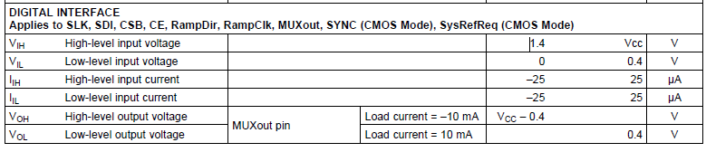
We are using LMK00804BPW as synchronizer for 3 other LMX2594RHAR. The Q outputs of LMK are directly connected to the SYNC inputs of LMX without any series resistor or pull-up on the lines. A note in datasheet of LMK states: "Outputs terminated with 50 Ω to VDDO/2." does this mean a 50ohm pull-up to be connected externally? Could you please elaborate on this note?

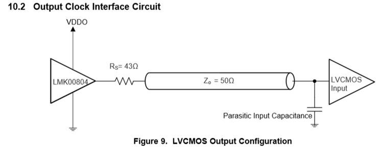
Also, In EVM of LMK, a 43ohm is used in series with the output. Should it be included in the design and how does it correlate with the 50ohm pull-up mentioned in the note above.


Thanks,
Sultan.

  • Hi Sultan,

    50 ohm to VDD/2 means the output is terminated to VDD/2 using a voltage divider with two 100 ohm resistors.

    Yes, use the 43 ohm series resistor for impedance matching. The 43 ohm resistor should be placed near the LMK00804B driver output at the start of the transmission line. 50 ohm termination is placed at the end of the transmission line, before the reciever.

    Kind regards,
    Lane

  • Hi Lane,

    Thank you very much for your response.
    Also, the Vol(max) of LMK is 0.5V but the Vil(max) of LMX is 0.4V. The condition for low state fails in this scenario. Please advice.


    Thanks and Regards,
    Sultan.

  • Hi Sultan,

    That VIL value refers to the LMX digital interface, not the clock input. This shouldn't be an issue for the clock input.

    Kind regards,
    Lane

  • Hi Lane,

    The LMK00804BPW  Q outputs are used to drive the SYNC pin of LMX2594 which is a digital interface with IO levels as stated in datasheet PFB:

    LMX2594:


    LMK00804B- Q outs: (powered at 3.3V)


    Both devices are powered with 3.3V lines, hence the output Vol(max) is taken as 0.5V while the Vil(max) is 0.4V. Please advice on how to handle this.

    Also, the resistor divider to VDDO/2 should come between Zo trace and Receiver (shown below) according to my understanding. Please correct me if I am wrong.


    Best Regards,

    Sultan.

  • Hi Sultan,

    I see, thanks for the clarification. In this case, you might use 50ohm to GND rather than 50ohm to VDD/2 to get closer to the GND for the output levels.

    You could also apply VDDO =2.5V or VDDO = 1.8V with VDD = 3.3V.

    You are correct, the receiver termination comes after the transmission line, at the receiver input.

    Kind regards,
    Lane