This thread has been locked.

If you have a related question, please click the "Ask a related question" button in the top right corner. The newly created question will be automatically linked to this question.

CDCE6214: Settings for operating in Pin Mode

Part Number: CDCE6214

Dear TI Team

Our customer is considering CDCE6214RGET.
However, due to the specifications of your application, you need to use CDCE6214RGET instead of I2C.

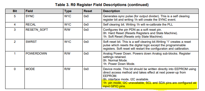
Looking at the data sheet, I think that there is the following Pin Mode, which makes it possible to use it without using I2C.

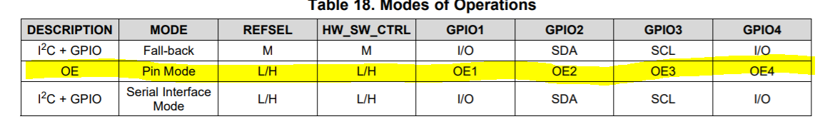
What kind of settings (terminal settings, register settings, etc.) are required to use CDCE6214RGET in Pin Mode?
I couldn't find the detailed description in the data sheet, so please let me know.

Best Regards,

Y.ottey

  • Hi Y.ottey,

    First of all by factory default, the page 0 EEPROM has pin mode enabled, meaning that the 4 GPIO pins are configured as individual OE pins.

    R0[0] defines the pin mode, but this bit will only take effect when written to EEPROM. More register details can be found here: 

    Regards,
    Hao

  • Dear Hao

    Thank you for your reply.

    "First of all by factory default, the page 0 EEPROM has pin mode enabled, meaning that the 4 GPIO pins are configured as individual OE pins."

    From the above, is it okay to recognize that GPIO pins 1 to 4 can be used as OE pins without changing the Resister because Pin Mode is enabled by default at the factory?

    ”R0[0] defines the pin mode, but this bit will only take effect when written to EEPROM. ”


    Also, does that mean that by default, the R0 registers are highlighted?

    Best Regards,

    Y.Ottey


  • Hi Y.Ottey,

    Yes by default GPIO1 through 4 function as OE1 through 4 that control output 1-4 individually, when EEPROM page 0 is selected. That also means, however, that I2C communication is not available.

    So in the default EEPROM page 0, R0[0] = 1

    Regards,
    Hao