Hi,
We are using a CDCI6214 clock output (AC-LVPECL @100MHz, 2.5V supply) to feed the serdes differential clock (SD1_REF_CLK_P/N) of NXP T1024 CPU, with max 0.8V differential allowed.
We are having some PLL sync problems with this clock.
We connected that clock as diagram below:
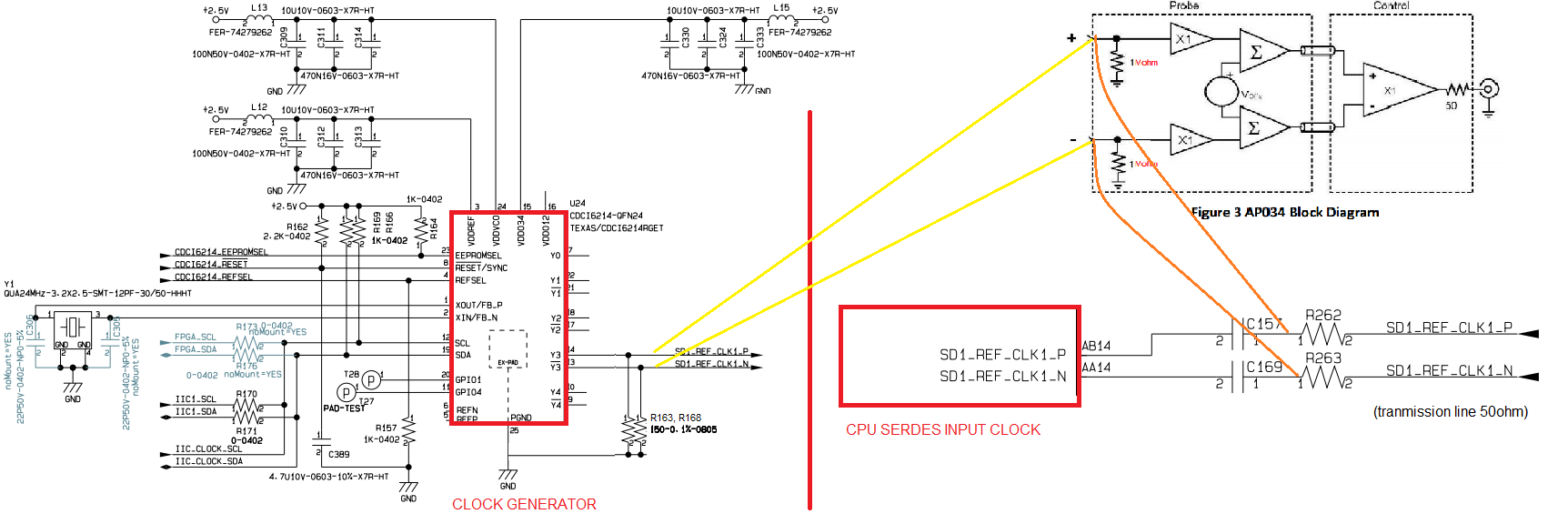
[CDCI6214 AC-LVPECL clk source P] --- [TX line 50ohm] ---- [22ohm*] --- [100nF] --- [SD1_REF_CLK_P, on T1024]
[CDCI6214 AC-LVPECL clk source N] --- [TX line 50ohm] ---- [22ohm*] --- [100nF] --- [SD1_REF_CLK_N, on T1024]
* = the 22ohm resistor is put because AC-LVPECL has Vpkpk=0.9V while the CPU accepts only 0.8V so that resistor gets a 0.7 moltiplication factor.
I know that AC-LVPECL is not standard: I wonder if using CDCI6214 with output clock differential AC-LVPECL @100MHz we'd better to put also a 150ohm to ground at source side.
My doubt originates because figure 8 in datasheet doesn't show any 150ohm termination at source side (so we didn't put this resistor) but generally a LVPECL needs a 130-150ohm to GND.
Moreover measuring the clock at source side with a FET probe with 150ohm to GND on both clock signals we obtain 1.8Vpk-pk instead that expected 0.9Vpk-pk.

Thank you,
Cheers,
Giacomo.