This thread has been locked.

If you have a related question, please click the "Ask a related question" button in the top right corner. The newly created question will be automatically linked to this question.

BQ32002: clock information reset when the system is reset

Part Number: BQ32002

Hello TI experts,

my customer use BQ32002 on their product, L2 ethernet switch.

the problem is as below;

1. in the middle of production, power on the device, and insert the time information through command window.

2. check that the clock is going well when the power is still on.

3. power is down, and complete production.

4. after the production complete, power on again for more tests. in this time we found that the clock is initialize to 1st Jan 1970, 00:00

5. if this happens, we replace BQ32002 with new one on reel tape. and do again from 1 to 4, then the problem disappear. so it is not the problem of oscillator or backup battery.

I attach a power-on log of both situation.

-- the log when the set time is deleted on second power-on (step 4)

************************************************************
* *
* Boot Loader Version 01.90.0001 *
* DASAN *
* *
************************************************************
Press 's' key to go to Boot Mode: 0
[Loading OS2 image ...]
[Image OK : os2]
Image Name: !NOS&V3024V&2.01&0001&
Image Type: ARM Linux Kernel Image (gzip compressed)
Data Size: 44995983 Bytes = 42.9 MB
Load Address: 81008000
Entry Point: 81008000
Verifying Checksum ... OK
Uncompressing Kernel Image ... OK

Starting kernel ...

SF: Unsupported flash IDs: manuf 00, jedec 0000, ext_jedec 0000
Disabling outer cache
rtc-ds1307 0-07-0068: hctosys: unable to read the hardware clock
INIT: version 2.85 booting
Mounting File Systems
0x00
0x00
Extracting configuration
Thu, 01 Jan 1970 09:00:06 +0900
INIT: E
V3024V login:

-- the log when the set time is saved successfully on second power-on (step 4)

***********************************************************
* *
* Boot Loader Version 01.90.0001 *
* DASAN *
* *
************************************************************
Press 's' key to go to Boot Mode: 0
[Loading OS2 image ...]
[Image OK : os2]
Image Name: !NOS&V3024V&2.01&0001&
Image Type: ARM Linux Kernel Image (gzip compressed)
Data Size: 44995983 Bytes = 42.9 MB
Load Address: 81008000
Entry Point: 81008000
Verifying Checksum ... OK
Uncompressing Kernel Image ... OK

Starting kernel ...

SF: Unsupported flash IDs: manuf 00, jedec 0000, ext_jedec 0000
Disabling outer cache
INIT: version 2.85 booting
Mounting File Systems
0x00
0x00
Extracting configuration
Wed, 13 Jan 2021 09:07:10 +0900
INIT: Ent
V3024V login:

--

as you see, the only difference is the red highlighted line.

could you advice where should I check to solve this problem?

please check this issue. Thanks.

Best regards,

Chase

  • Hi Chase,

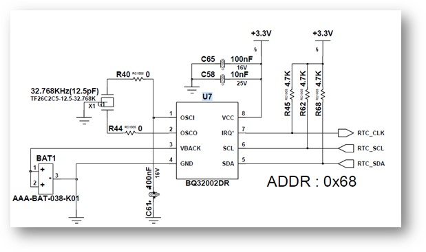
    Can you share the schematic and part number for the XTAL?

    When you power down the system and power back on after production, you must have a battery powering the RTC. What is the battery voltage when turned back on? If Vbackup drops too low, it is expected that the RTC would lose power and lose the time setting.

    When you receive the error message of unable to read the RTC, this tells me the device may not be responding to the I2C communication. Are you able to reprogram the registers to set the time, and read back the time to confirm I2C communication is working?

    Kind regards,
    Lane

  • Hi Lane,

    Thank you for your response.

    1. I attach the schematic below;

    2. I requested the specification of X-TAL and backup battery, i will send it to you as soon as possible.

    3. the problem is, when I face the reset situation, it is okay if I replace it to new one. this is why I don't doubt X-TAL and backup battery.

    if the X-TAL or backup battery have problem, reset would appear again even I replace the part.

    4. Yes, I can reprogram the registers to set the time, and read back the time while the power is still on. it works with no problem.

    Please check this issue. Thanks.

    Best regards,

    Chase

  • Hi Lane,

    Please check attached files for the specification of X-TAL and backup battery.

    Please let me know if you get something.

    Best regards,

    Chase

    CR2032H.pdf

    TF26C2C5-12.5-32.768K.pdf

  • Hi Chase,

    Thanks for the information. The XTAL and backup battery datasheets look OK, and no apparent issues with the schematic.

    It still may be helpful to measure the battery voltage before powering the system back on in step 4 just to confirm the voltage is within the recommended range.

    When removing/replacing the battery, this can cause a high current state and would drain the battery faster. This is discussed in datasheet section 8.2.2.3. Be sure to always apply the pulse on VCC immediately after connecting the battery following a total power loss scenario.

    It may also help to check whether the oscillator is functioning for the "bad" device after step 4. You can do this by clearing then reading the OF bit, reading back the time to see if it increments properly, and probing the XOUT pin.

    We may be able to provide some additional offline support if you can send us an email at cts_rtc_nt_flex@list.ti.com

    Kind regards,
    Lane

  • Hi Lane,

    i am still wondering that is is not all the BQ32002 not working, just few of that do not work.

    as i said, when the customer found this in production line they replace RQ32002 to new one in the reel tape. and it work again. so i thought that it is not the matter of schematic or X-TAL or backup battery, it is the matter of BQ32002 only.

    but still i don know, the only difference between faulty and normal is the power down and re-power-on operation, clock information reset or not.

    so i thought this is the matter of internal register or something. because the waveform of external pins using oscilloscope look same between faulty and normal ic.

    what do you think about this? can you give me some advice?

    Best regards,

    Chase

  • Hi Chase,

    It still may be helpful to measure the battery voltage before powering the system back on in step 4 just to confirm the voltage is within the recommended range as it will let us know if the battery voltage is marginal to the requirement of 1.4V .

    I would also be happy to review your register settings. Please send me the register dump from a working device and bad device for comparison.

    It is not clear why some devices are faulty, this time reset issue has not been reported before. Send us an email at cts_rtc_nt_flex@list.ti.com and we can investigate this issue further offline. 

    Kind regards,
    Lane