This thread has been locked.

If you have a related question, please click the "Ask a related question" button in the top right corner. The newly created question will be automatically linked to this question.

LMK04826: 560ohm termination resistor on the LVDS clock path

Guru 11160 points
Part Number: LMK04826

Hello,

My customer is using the LMK04826 with the following clock output.

    1. DCLKOUTx : 245.76MHz LVDS clock for Device REFCLK

    2. SDCLKOUTx : 0.96MHz LVDS clock for JESD204B SYSREF

The customer found in the LMK04826 datasheet that a 560 ohm termination was required when using an interanl 100 ohm termination.

So, they tested the two cases below by adding a 560 ohm termination.

CASE1 :

There was no problem at DCLKOUTx 245.76MHz clock, but there was no output at negative line of  SDCLKOUTx 0.96MHz clock.
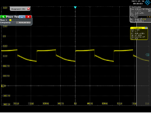
CASE2 :

There was no problem at DCLKOUTx 245.76MHz clock, but abnormal signal was output at SDCLKOUTx 0.96MHz clock as shown below.

Are the 560 ohm termination application conditions different depending on the output clock rate?

Please advise us what caused the issue and how to fix it.

Thank you.

JH

  • Hello JH,

    In case 2, is it possible to set the internal termination of the FPGA to open and the resistor to 100 ohms?

    73,
    Timothy

  • Hi Timothy,

    My customer has boards designed in two types, CASE1 and CASE2 respectively.

    They tested to add a 560ohm termination as recommended by TI in the latest datasheet.

    Please help us clear the problem in both CASEs using 100ohms inside the FPGA.

    Thank you.

    JH

  • Hello JH,

    Ok - for troubleshooting, how many boards has this been observed on?  Are there boards which have no trouble?  Can you advise which FPGA is being used?  I'd like to review it's input termination configuration info.

    For both cases, please momentarily short SDCLKoutx positive an negative outputs together and release.  Does the output begin to operate?

    For both cases, if the SYSREF divider is changed to provide an output of 245.76 MHz also, do the outputs operate normally?  Next, olease half the frequency and repeat test until break-point.

    73,
    Timothy

  • Hi Timothy,

    With you help, the customer found that the AC coupling cap was inserted incorrectly. Thank you for your help.

    Is there a guideline for selecing the AC coupling capacitor value based on clock type or frequency ? Or Is 0.1uF the perfect value?

    Best Regards,

    JH

  • Hello JH,

    For lower frequencies you may increase the value, the idea is to prevent the capacitor from noticeably discharging.  For example since this is a 50 ohm system, the time constant RC = 50 ohms * 0.1 uF = 5 us.  The frequency of 5 us is 200 kHz.  At 0.96 MHz, you're just under 5x the time constant, so you will probably see a small amount of discharge...  I don't see any issue with that practically, but using 1 uF would reduce the discharge.

    For higher frequencies, you have to look at the non-ideal nature of the capacitor, when you get to high enough frequency, often many GHz, the capacitor may actually become inductive and as you increase frequency the impedance of the component will increase.  In these cases often a smaller value like 100 pF may be considered.  Refer to the model for your capacitor to see at what frequency it becomes inductive and if you're ok with the reactance of the capacitor at the frequency.

    But for most cases, the 0.1 uF is a fine value.

    73,
    Timothy