


Other Parts Discussed in Thread: LMK04808
I have a customer designing with LMK04828.
They are using the Crystek CVHD (at a different frequency). Here are their questions:
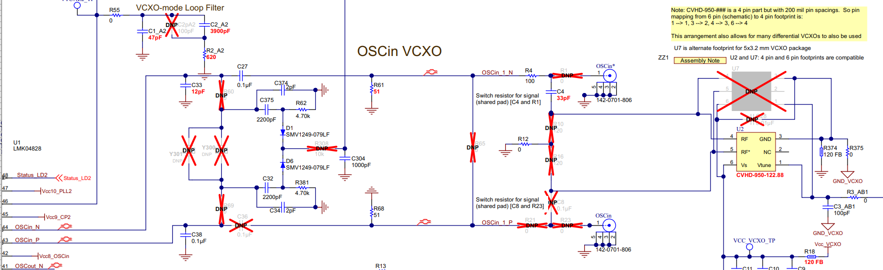
Presumably, when XTAL is used, C4 would be DNP C4?
R10, R16, C8, C36 would be fitted to connect the XTAL to OSCin_P? Some of these capacitors are used to match the input to the VCXO?
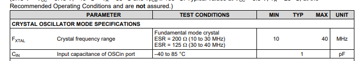
The CVHD has a load capacitance of 14pF, whilst I believe the LMK presents a 1pF input. I might be misreading the datasheet as the section is as follows:
I know that the OSCin for PLL2 supports frequencies up to 500MHz.
Can you clarify input capacitance of the OSCin port?
Any guidance for presenting the correct load capacitance for the VCXO?
