A related question is a question created from another question. When the related question is created, it will be automatically linked to the original question.
If you have a related question, please click the "Ask a related question" button in the top right corner. The newly created question will be automatically linked to this question.
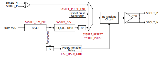
Please refer to Datasheet Figure 7-4: SYSREF Functional Diagram.
The f_INTERPOLATOR should be either 800MHz to 1600MHz or 500MHz to 1500MHz, this will be coming from the device itself not external, therefore the SYSREF will be less than or equal to 187.5MHz.
However, if SRREQ input is passed through, the re-clocking circuit operates at 400 to 800MHz or 250 to 750MHz.
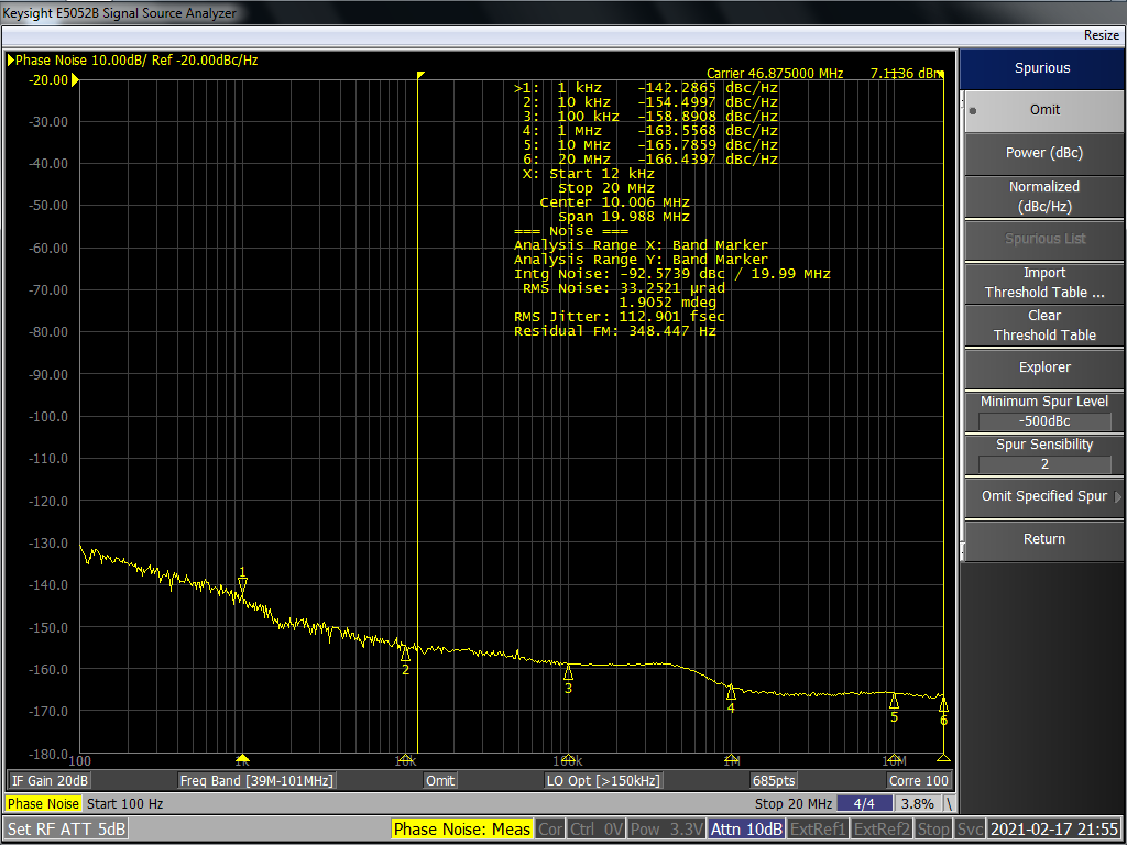
Can you please let me know the VCO frequency you plan to use? I can take the plot of the 32MHz SYSREF clock, but I need to know how the SYSREF is to be configured for your use case.
It isn't possible to reliably generate 32.665MHz SYSREF frequency through the dividers on the LMX2820 when the VCO is set to 8884.2MHz. Refer to the diagram below:
In order to get 32.665MHz from 8884.2MHz, you must divide by 272. Additionally, the SYSREF_DIV_PRE output frequency (the interpolator frequency) must be between 800MHz and 1600MHz. This is only possible by setting SYSREF_DIV_PRE to divide-by-8. 272 / 8 = 34. Additionally there is a divide-by-2 block after the SYSREF_DIV, so the remaining SYSREF_DIV must be 17; this is not possible, since the SYSREF_DIV only includes even divides. If you try to use SYSREF_DIV_PRE with divide-by-4, the programmable delay steps will likely become nonlinear and will no longer work.
In practice, it is possible to get 32.665MHz by ignoring the limits on the interpolator frequency and setting the SYSREF_PRE_DIV to 4:
The output performance of the SYSREF clock will be degraded compared to the device clocks. Otherwise, the output format, common mode, and other behavioral characteristics are the same as the RF output buffers. Into high-impedance I measure around 2V common mode voltage, with a low of 1V and a high of 3V, at each pin. Expect the amplitude to be reduced by about half when driving a 50Ω load.
I appreciate your effort and time spent for sending me this phase noise plot. Thank you very much. The phase noise matches my requirement.
I may not require exactly the clock 32.665 MHz, my SYSREF clock will be in the range of 32MHz to 32.700 MHz.
Why and how the performance of the SYSREF clock will be degraded compared to the device clocks. I want to use this pure clock for continuous sampling the analog signal through ADC.
Is it recommended ?.
Request you to share the differential voltage swing of the SYSREFclock.( VODIFF max and VODIFF min).
Compare the phase noise plot below, taken from the channel divider maximum divide at an arbitrary VCO frequency, vs. the SYSREF output phase noise data in the previous post. There is around 10dB worse performance at the SYSREF noise floor, and the RF output is 1.5x higher frequency.
I don't have any data on the SYSREF VODIFF min/max, because as far as I can tell this has not been characterized. Based on the previous post phase noise plot, it looks like just under 10dBm output power differential into 100Ω load (measured through a 2:1 impedance balun into 50Ω single-ended), which is just under 2Vpp VOD.