This thread has been locked.

If you have a related question, please click the "Ask a related question" button in the top right corner. The newly created question will be automatically linked to this question.

LMX2572: lock duty cycle

Part Number: LMX2572
Other Parts Discussed in Thread: LMK00304

Hi team,

My customer is having PLL lock problems with the LMX2572.  If the reference clock to the part does not have a 50% duty cycle the PLL will not lock. They are not using the frequency doubler.  A need for a 50% duty factor is not mentioned in the datasheet. They intended to use a 30% duty cycle, but it will not lock.  This was tested with the eval board.

Could you confirm that this part requires about a 50% duty cycle to lock and please provide the minimum reference clock duty cycle?

Thanks,

Connie

  • Hi Connie,

    We will get back to you next Monday.

    Regards,
    Hao

  • Hi Connie,

    This is the first time I hear somebody want to use 30% duty cycle reference clock for a synthesizer, do you know what is the reason for this design?

    If they are not using the OSC_2X doubler and the MULT multiplier, theoretical speaking, the synthesizer should lock. Can they confirm, the synthesizer will lock if they adjust their reference clock to 50% duty cycle?

  • Hi Noel,

    Yes, they can confirm it will lock with a 50% duty cycle in their test set-up.

    The reason for the 30% duty cycle is that they are using the LMK00304 for the clock and it receives a low amplitude (~ 0.3Vpp) signal.  This causes a 30% duty cycle clock out of the clock buffer to the PLL.  The LMK00304 is self-biasing (not per the datasheet).

    Could you confirm what the minimum reference clock duty cycle is on LMX2572?

    Thanks,

    Connie

  • Hi Connie,

    We seldom measure the performance with a non-50% duty cycle reference clock, as this is not a common use case for PLL/synthesizer, we don't have test data in this regard. As I said before, in theory, it should lock as the R-counter will only look for the rising edge of the reference clock, so the duty cycle is not matter. 

    Is the VID to the LMK00304 = 0.3V? If this is the case, it should be fine. The spec of LMK00304 is asking for 0.15V min. 

    I am guessing that the lock issue is not due to duty cycle but the quality of the reference clock. I suspect, except for the duty cycle, the phase noise and cycle-to-cycle jitter are also bad. I think our focus should be on fixing the buffer issue instead of trying to tweak the synthesizer (I am not sure if this is possible), it is not a wise decision to provide a bad quality reference clock to a synthesizer.

  • Hi Noel,

    Thanks for the guidance. Could you take a look at the reference clock or loop in whoever is in charge of LMK00304?

    Below is the 200MHz, 500mVpp reference clock driving the LMK00304. 


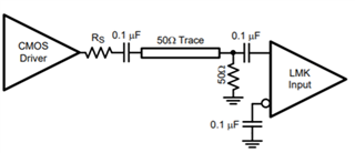
    The input to the LMK00304 is like this:


    But with an LVPECL driver (no Rs).

    The output of theLMK00304 is a non-50% duty cycle square wave.

    Thanks,

    Connie

  • Hi Connie,

    This input signal looks good to me, I am surprise that the output duty cycle is 30%. I will ask my colleague to support the buffer issue.

  • Hi Noel,

    Is there any response on this or someone looped in for LMK00304?

    My customer could get 50% duty cycle out of the LMK00304 after adding a PECL clock buffer. Any idea why the signal earlier didn't work?

    Thanks,

    Connie

  • Hi Connie,

    It makes more sense to provide the differential LVPECL input to CLKin/CLKin* rather than use only one of the differential outputs form the pair and LVCMOS clock termination

    If you were using an LVCMOS driver and running into this same issue with duty cycle distortion, consider the following debug steps:

    LMK00304 CLKin input has an internal bias of 1.4, however the clock's common mode voltage is GND in the waveform you shared. 

    You might check to confirm the clock input is connected to CLKin, and CLKin* is AC-coupled to GND.

    You can also measure the CLKin/CLKin* pins to check the DC bias.

    You might also try to DC-couple the clock input like figure 26.

    Kind regards,
    Lane