This thread has been locked.

If you have a related question, please click the "Ask a related question" button in the top right corner. The newly created question will be automatically linked to this question.

LMK05028: XO input in case of DC coupled LVDS

Part Number: LMK05028

Hi all

Would you mind if we ask LMK05028?

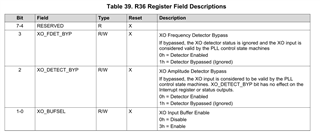
On the Table4, it shows XO input Buffer modes.


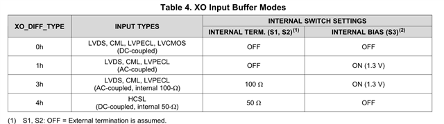
On the figure 31, there is the despcription in case of DC-coupled LVDS.
It seems that there is internal termination. 

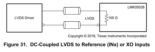
However, on the Table4, in case of 0h, it could not choise internal termination on setting.
So, as the conclusion, in case of DC coupled LVDS, we should use external termination = 100ohm, right?

Kind regards,

Hirotaka Matsumoto


  • Hi Hirotaka -san,

    Yes the table is a bit confusing, the GUI also doesn't allow DC and internal termination:

    However, there's workaround with manual programming.

    As you can see on Figure 26, the signal is always internally AC coupled as the 28 pF capacitor is always on. However the "AC coupled" in table 5 means that externally there are AC coupling capacitors such that the driver does not set a common mode and the internal weak bias must be turned on.

    By programming 2h into the interface type registers (get this information via GUI, has to be done in RAW registers tab as is not part of the drop down menu) you will be able to use internal termination of 100 ohm. Signal must have common mode voltage of ~1.25V and meet the swing requirements.

    Thanks and regards,

    Amin

  • Amin san

    Thank you for your reply.

    We would like to confirm one point.

    Using XO_DIFF_TYPE=2h, is it possible to configure followings?
    -INTERNAL TERM. (S1, S2) = ON, internal termination 100ohm
    -INTERNAL BIAS (S3) = OFF

    On the other hand, is it possible to use XO_DIFF_TYPE=3h for DC coupled LVDS?
    Actually, there is the week bias voltage, so it depends on the proterction of external connection LVDS driver.


    Kind regards,

    Hirotaka Matsumoto
     

  • oh sorry I thought the question was with regards to reference input.

    You have an Oscillator that provides a DC coupled output? What is the common mode?

    Amin

  • Amin san

    You have an Oscillator that provides a DC coupled output? What is the common mode?
    ->Yes, DC-coupled output, and then VOS=1.25V. And we mentioned XO input.

    There is the difference between register map(SNAU233) and the datasheet as follows;

    On the register map Table 41
    3-0 XO_DIFF_TYPE R/W X
    0h = 2.5-V LVCMOS or DC-DIFF (Internal termination and biasing off)
    1h = AC-DIFF (Internal termination off and biasing on)
    2h = AC-DIFF (Internal 100-Ω differential and biasing on)
    4h = HCSL (Internal 50-Ω to GND and biasing off)

    On the data sheet Table.4 ;
    0h LVDS, CML, LVPECL, LVCMOS(DC-coupled)
    1h LVDS, CML, LVPECL(AC-coupled)
    3h LVDS, CML, LVPECL(AC-coupled, internal 100-Ω)
    4h HCSL (DC-coupled, internal 50-Ω)

    Which is the correct?
    Unless we confirmed with TICSPRO, it looks that the datasheet's table is correct.

    Kind regards,

    Hirotaka Matsumoto

  • Amin san

    If you have some update for our last post, could you share us?

    Kind regards,

    Hirotaka Matsumoto

  • Hi Hirotaka -san,

    Yes, 3h should be for AC-DIFF (internal 100 ohm).

    I believe the same method of 2h should work for DC with internal 100 ohm but let me double check with designer.

    Thanks and regards,

    Amin

  • Hi Hirotaka -san,

    I have confirmed with designer - reference path and XO input share much of the same circuitory design. To enable internal 100 ohm and DC coupled input, XO interface type R36[1] = 1. R36[0], R36[2], and R36[3] = 0. (if you step through the interface type selections on main start tab, this will make sense). Recommended common mode is ~1.25V.

    Thanks and regards,

    Amin

  • Amin san

    Thank you for your reply.

    On LMK05028's regsiter map, R36 shows as follows.


    You mentioned follows;
    "XO interface type R36[1] = 1. R36[0], R36[2], and R36[3] = 0"
    It seems that XO Input Buffer Enable=1 is not defined. Is it correct?

    Kind regards,

    Hirotaka Matsumoto

  • Hi Hirotaka -san,

    R38, hex value 26. Typo on my part. Have you used TICSpro? If you install and use you'll see once you start changing the XO input types which register is being updated in the dialog box.

    XO interface type:

    1. LVCMOS/DIFF (ext. term): 10h - 0001 0000
    2. AC-DIFF (ext. term): 11h - 0001 0001
    3. AC-DIFF (int. 100R): 13h - 0001 0011
    4. HCSL (int. 50R): 14h - 0001 0100

    We want: 0001 0010 - 12h. That should enable internal 100 ohm. That should enable switch 2, disable switch 3. When you program the raw register the field in the GUI will go blank since it hasn't been updated to support DC coupled internal termination yet.

    Thanks and regards,

    Amin

  • Amin san

    Thank you for your cooperation!
    OK, we got it!

    Kind regards,

    Hirotaka Matsumoto