Part Number: LMX2491
Hi Team,
Can you advise me on my question, related to the LMX2491 reference schematic diagram.
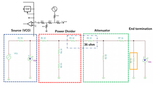
Referring it on the data sheet, the output from the external VCO is connected to the FIN pin,
through a 50 ohm power divider and a -6dB attenuator.
The 50 ohm power divider consists of three 18 ohm resisters connected as star topology,
the -6dB attenuator composed with two 18 ohm resisters and one 58 ohm resister as T shape
topology.
I think that a 50 ohm resister is necessary on the FIN pin, to make them work as intended.
If it is true, the 51 ohm resister on *FIN may be replaced with a 51/2 ohm resister to make
the circuit symmetry.
What do you think of it?
The second question:
If power divider and attenuator make the VCO output totally -12 dB, the power delivered to the
PIN pin is -11 to -8 dBm, because the VCO output power is 1 to 4 dBm.
In contrast, the expected power level of FIN input is -6 to 6 dBm.
How do you deal with this mismatch?
Mita