This thread has been locked.

If you have a related question, please click the "Ask a related question" button in the top right corner. The newly created question will be automatically linked to this question.

ADS1274: EVM can not sampling

Part Number: ADS1274
Other Parts Discussed in Thread: ADCPRO, ADS1278,

Hi Team,

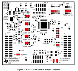
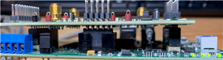
The customer purchased evaluation boards of ADS1274EVM.RevG and MMB0.RevD from TI official website,

Then the client downloaded ADCPro software and tried to evaluate ADC function.

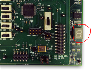
On the day of download, J3 on ADS1274EVM.RevG is open, and then it can sampling and obtain waveform.

But the next day, I started the computer. This time, I shorted J3 to make input on short-circuit state, and then I tried to sampling,

I got uutput error code of "error code 6070", it can not sampling.

BTW, NI-VISA's USB driver doesn't exist on the computer.

But yesterday the driver still existed.

Even if I look at the device drivers of the PC management,

There is no unknown device.

Therefore, it is natural that ADCPro cannot communicate with ADS1274EVM.
This failure occurs on Windows 10 PC.
For the sake of caution, I installed ADCPro on the windows 7 PC for confirmation, the evaluation board still can't sampling.

Then, I confirmed the D + and D- terminals of USB-B of MMB0 are synchronized,

Both terminals are always at a low level, and there is no data exchange at the moment of connecting with PC.

From the above failure, can you help me analyze the MMB0 hardware failure or not?

Or any other reasons?

thank you!

Regards,

  • Hello Frank,

    My understanding is that the ADS1274EVM worked correctly the first time software was installed and the board was powered up.  Please confirm that you were able to power the ADS1274EVM, connect to the GUI, and collect data when first installed.

    Once you are able to connect to the EVM and use the software, there are usually not any additional communications problems related to software.  This could be hardware related:

    1.  Please connect power and verify the supply voltages on J5.  

    a)  Measure AVDD, J5-3 to J5-6, should measure +5V typical

    b)  Measure DVDD, J5-7 to J5-5, should measure +1.8V typical

    c)  Measure IOVDD, J5-9 to J5-5, should measure +3.3V typical.

    d)  The LED display on the MMB0 board should be illuminated.

    2.  Verify the Default Jumper locations are correct, Figure 1 in the User's Guide.

    3.  Try using a different USB cable.

    4.  Plug the USB cable into a different USB port on your Windows 10 machine.

    5.  Uninstall the ADS1274EVM GUI software, reboot PC, and re-install software.

    Please let me know if any of the above suggestions helps solve the problem.

    Regards,
    Keith Nicholas
    Precision ADC Applications

  • Hi Keith,

    Thank you for your advice.
    I confirmed the jumper position of "2." as shown in the photo you prompted.

    For 7-segment LED,
    If the sampling is successful, the light in the LED section will rotate,
    But without sampling, all the LED segments are off.

    In addition, the following items have been confirmed.
    Unfortunately, none of them worked.

    "3. Try to use a different USB cable."

    "4. Plug the USB cable into another USB port on your Windows 10 computer."

    "5. Uninstall the ads 1274 EVM GUI software, restart the PC and re install the software."

    As for "1." now I will confirm it,
    and I will update this post after confirmation.
    Thanks.
    Regards,

  • Hi Keith,

    Regards to the measured voltage of "Question 1".
    "1. - D) there is a content," Please light up the LED display on the mmb0 board. "

    Does this LED refer to 7-segment LED?
    But I don't know how to turn on this LED.
    Therefore, I measured all the voltage on the J5 when the LED is not illuminated

    The results are as follows.

    J5-1 = 0V

    J5-2 = 0V

    J5-3 = 4.99V

    J5-4 = 0V

    J5-6 = 0V

    J5-7 = 1.81V

    J5-8 = 0V

    J5-9 = 3.31V

    J5-10= 4.99V

    Please confirm.
    Thanks.

  • Hello Frank,

    All voltage measurements on J5 are correct; the board has power.

    Please re-install the ADS1278 plug-in software for ADCPro (ADS1278EVM-PDK-SW).  This software installs the drivers for the evaluation board.

    Also, please confirm that J3, J4, and J5 are properly aligned and connected to the MMB0 board.  It may be possible that power is getting to the ADS1278EVM board through J5, but the EEPROM communications is not properly connected.

    Regards,
    Keith

  • Hi Frank,

    My apologies.  I mean to re-install the ADS1274 plug-in software for ADC Pro (ADS1274EVM-PDK-SW).

    Also, here is a picture of the ADC EVM board properly connected to the MMB0 board.

    Regards,
    Keith

  • Hi Keith,

    I tried to re install ADS 1274 EVM-PDK-SW, but it didn't work.
    Then, ADCPRO was also re installed, but it still had no effect.
    J3, J4, J5 seem to be connected correctly.

    Here, I add an order for ADS 1274 EVM.
    Connected to this place, no problem sampling.
    Sure enough, the first evaluation board seems to have broken down.
    Once it's ready to sample, it doesn't work the next day.
    During this period, it is possible to put pressure on the substrate.
    Then, is there anything to pay attention to when I use this evaluation board?


    Thanks.
    Regards,

  • Hi Frank,

    Yes, I think the board is broken and you need a new ADS1274EVM.  I have not had any issues with these boards; they work well as long as all jumpers are correctly installed and the ADS1274EVM and MMB0 boards are properly connected together.  You must have received a board with a bad solder connection that works sometimes and others does not.

    Hopefully your replacement board will work without any problems.

    Regards,
    Keith