This thread has been locked.

If you have a related question, please click the "Ask a related question" button in the top right corner. The newly created question will be automatically linked to this question.

ADS1247: ADS1247 single-ended measurement data suddenly changes

Part Number: ADS1247

Hi Sir,

We are using ADS1247 and Pt100 to measure temperature, but when charging, there will be a sudden change in the measured temperature value (the end equipment have battery inside). 

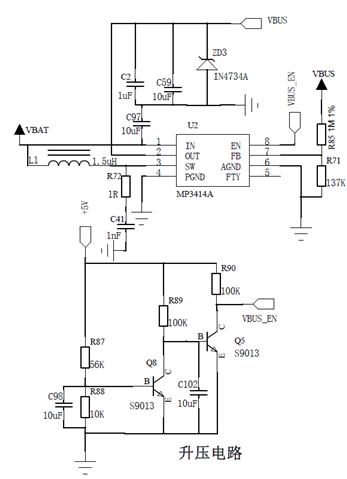
Here is my schematic:

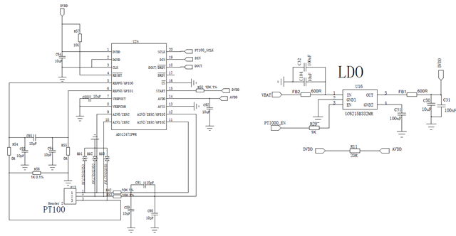
As u can see from the schematic diagram, the /DRDY pin is in a floating state. Will this cause the previous problem? Or u can give some better suggestion to this problem?

Thanks,

Best Regards

  • Hi Lumina,

    but when charging,

    Can you explain what this means? Is this related to the battery charging up? Or something else?

    Does this issue only occur when the battery is charging, and then every other time it is okay? Are there spikes or drooping on the power supplies when the charging occurs? I think you will need to provide more information on what is going on when the issue occurs, as well as provide information on how the data is wrong.

    The DRDY pin is an output from the ADC, so it should be okay to leave floating. In fact, the datasheet recommends this condition.

    -Bryan

  • Hi Bryan,

    The device is equipped with a 6000mAh rechargeable lithium battery.

    When the device works with the built-in battery without adapter, the PT100 is placed in a constant temperature tank and the temperature can be measured to fluctuate within the normal range. But when plugged into the adapter, the measured temperature fluctuates within a few degrees (the tank temperature fluctuates within 0.05 degrees).

    We tried to control the output ripple of the adapter within 50mV, and the temperature also fluctuated to 1 degree.

    We are wondering if the schematic added previous is correct and how to solve this problem. I also added the power supply circuit to the below and hope it can do some help for the analysis.

    Thanks,

    Kind Regards

  • Hi Lumina,

    One thing I noticed from the original schematic you sent is that the input filtering cutoff is very high. The 2x 10k resistors + 10pF cap give you a cutoff around 800 kHz. In reality, the cutoff should be somewhere around 2-10kHz, depending on your data rate. This FAQ might help explain why this is necessary: https://e2e.ti.com/support/data-converters-group/data-converters/f/data-converters-forum/955466/faq-delta-sigma-adc-anti-aliasing-filter-component-selection

    You should also have a matching filter (as much as it is possible) on the reference inputs. Right now you don't have any resistance in that path, just 0ohm resistors.

    I am not sure how much this will help the issue you are having, but it would certainly be best practice to make these changes.

    Do you know where the noise is entering the system? If you measure the ADC inputs with a DMM, do you see the fluctuations? If not, can you then measure the supplies to see if they are changing while the system is charging? We need to try to narrow down how the noise enters your system to know how to improve it. I suspect you might be seeing some ground bounce where the battery charging is somehow moving the ADC ground up and down, causing the data errors.

    -Bryan