This thread has been locked.

If you have a related question, please click the "Ask a related question" button in the top right corner. The newly created question will be automatically linked to this question.

DAC7760: Problem with user calibration and bit resolution

Part Number: DAC7760
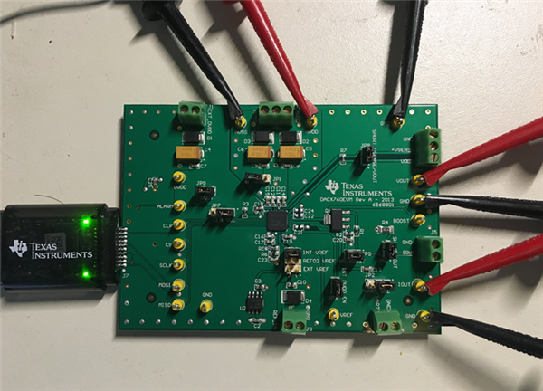
Other Parts Discussed in Thread: , DAC8760EVM, DAC8760

We are using 4 daisy chained DAC7760 devices on our propriety board and having some problems with readings. Our design is expected to be able to configure anyone of the 4 inputs for 0V to 10V or 4mA to 20mA.

Question 1:
According to formula on page 28, when CODE set to 1, Should I be expecting the voltage on the output to be 0.0024414 (~2.4mV) as when increment CODE by 1, I am seeing the result in table laballed RESULT A. as shown below in code section because of formatting


VREF = 5V
GAIN = 2 (0V to 10V from Table 1 page 28)
N = 12
2^N = 4096

Unipolar Mode:
VOUT = VREF * GAIN * (CODE/2^12)

For CODE = 1
VOUT = 5 * 2 * (1/4096)
VOUT = 0.0024414


Question 2:
According to Equation 6 in DAC7760 datasheet page 34 the following formula is given.
CODE_OUT = CODE * ((User_GAIN + 2^15)/2^16) + User_ZERO

For the DAC7760 the value of 2^15 would that be 2^11 ie N-1?

Question 3:
Are there any other Application not that can help provide additional clarity for the use of the DAC7760.

-----------------------------------------------------
Address |           Register                   |  Value
-----------------------------------------------------
0x01    | Write DAC Data register              |  Code - see below
0x55    | Write control register (0to10V)      |  0x1009
0x55    | Write control register (4to20mA)     |  0x100B
0x57    | Write configuration register         |  0x0020
0x58    | Write DAC gain calibration register  |  0x0800
0x59    | Write DAC zero calibration register  |  0x0000

RESULT A:
Code   |  Output
-------|--------
0x0000 | -0.0020
0x0001 |  0.0004 
0x0002 |  0.0028 
0x0003 |  0.0052    
0x0004 |  0.0077
0x0005 |  0.0102 
0x0006 |  0.0126
0x0007 |  0.0150
0x0008 |  0.0175
0x0009 |  0.0200 
0x000A |  0.0224 
0x000B |  0.0248     
0x000C |  0.0273
0x000D |  0.0297 
0x000E |  0.0321
0x000F |  0.0345

Address |           Register               Value
-------------------------------------------------
0x58    | DAC gain calibration register |  0x0800
0x59    | DAC zero calibration register |  0x0001

RESULT B:
Code   |  Output
-------|--------
0x0000 | 0.0004
0x0001 | 0.0004 
0x0002 | 0.0028 
0x0003 | 0.0052  

  • Ola,


    1. I think the results will make more sense if you set the DAC gain calibration register to 0x8000. This would set the gain calibration to 1. If you set the gain calibration register to 0x0800, this sets the gain calibration to a little over 0.5, which makes the maximum output about 5.3V and can make the output skip codes. Because the device is 12bits, and the DAC output code is left justified, I use the following output codes and get the output voltage without the calibration enabled:

    0x0000 - 0.0000V
    0x0010 - 0.0024V
    0x0020 - 0.0049V
    0x0030 - 0.0073V
    0x0040 - 0.0098V

    If I enable the calibration, and I set Gain Calibration to 0x8000 (again left-justified), this sets the gain to 1, allowing the full 10V of range. Then I set the offset calibration to 0x0010, I get the following:

    0x0000 - 0.0024V
    0x0010 - 0.0049V
    0x0020 - 0.0073V
    0x0030 - 0.0098V
    0x0040 - 0.0122V

    Which appears correct, where the LSB is 2.44mV and the full-scale range is 10V

    2. For the DAC7760, the gain calibration code is still 2^15. To get a gain of 1, you use User_GAIN = 0x8000. A User_GAIN of 0x0800 gives a gain of about 0.53.

    3. I used the DAC7760EVM and its software to help answer these questions. I find that having the GUI can quickly get expected answers on how things should run on the device. Its a convenient way to test the registers and see what outputs you will get from the device.


    Joseph Wu

  • Hi Joseph,

    Thanks for your reply.

    1. Yes I am setting the gain to 1 as I shift left by 4 before writing the data so 0x0800.

    void dac7760::WriteGainCalibrationRegister(uint16_t dac1, uint16_t dac2, uint16_t dac3, uint16_t dac4)
    {
      dac4<<=4; dac3<<=4; dac2<<=4; dac1<<=4;
      writeRegister(DAC7760_WR_DAC_GAIN_CAL_REG, dac1, dac2, dac3, dac4);
    }

    The reason I wrote the API this way was to respect the fact that the destination DAC Gain Register was 12-bit and the user of the driver may be wondering why is it allowing 0x8000 to be written knowing that it would overflow. I would consider removing the shifts left and simply allow the 0x8000 to be written.

    2. Thanks for pointing out the 2^15 mistake I was making. I thought this was an error in the datasheet. That explains why I was getting some silly values when I was assuming that this value was N-1. All the values I calculated for CODE_OUT was not making sense when compared to CODE value

    3. It is amazing you mentioned DAC7760EVM as I just gone mine delivered today and currently in the process of setting it up.


    I would report back on how far I get. Once again thanks

    Regards

    Ola

  • Ola,

    Ok. Let me know how far you get.

    I do think that the EVM is a really convenient way to help evaluate the device and check for any problems in operation. These devices can be complex and it's easy to miss something simple.

    Joseph Wu

  • Hi Joseph,

    I seem to be having problems with the EVM board or USB dongle. The DAC8760EVM application itself is running fine. When I click some of the command buttons I can see that it is correctly building up the commands by looking at the Register tabs. However when I click the Write All Reg button followed by Read All Reg button all I get back is zeros.

    After trouble shooting I noticed that I am not seeing any voltage on DVDD or VDUT. Is there a trick I am missing to get the SM-USB-DIG Platform to supply voltage to the EVM board?

    Also should VDUT LED in the SM-USB-DIG Platform be lit when operating correctly? sometimes I see it light up and then subsequently goes off and sometimes it just stays lit.

    Regards 

  • Ola,


    For the DACx760EVM, I have everything set up in the following way:

    You do need an external supply, so I have AVDD connected to +12V, and AVSS connected to -2V. I'm using a dual supply and I also have a ground connection. I have JP1 disconnected (with JP1 connected, the AVSS is connected to GND. I have JP6 connected so I can use the onboard shunt to measure IOUT. I connect multimeters to VOUT and GND and then to IOUT and GND to measure the output.

    When you connect everything together, make sure the SM-USB-DIG connector is properly aligned (sometimes the connector can be one position in either direction). Also the TI logo is on the top, as shown in the picture.

    For the GUI, start by clicking the Auto-write changes button and leave it on. This updates the registers when I click on buttons or update values immediately. Then I click the Reset DAC8760 button (twice - once to enable, second to disable the reset).

    After that, I select the mode, enable the output, select Dual Output Enable, Set the Current Range, and then the Cal enable. I can also enter in DAC and calibration codes. At this point everything should be working and you should have an output on both IOUT and VOUT.


    Joseph Wu

  • Hi Joseph,

    Thanks for your detailed reply. My EVM board is now working. I believe the problem was the VDUT not turning on, this is responsible for powering the digital part of the board. To be honest I am not sure why it was not working before. 

    I would now continue with the rest of my test as I can now confirm that I can Write and Read the register correctly.

    I would let you know how I get on with the rest. Once again thanks 

    Regards

    Ola

  • Hi Joseph,

    I thought to give some feedback I now have things behaving as expected. The issue that I was having with the VDUT not turning on was due to the fact that I was launching the GUI application and then connecting the SM-USB-DIG connector. This was causing the VDUT to not supply the 5V that the digital part of the board needed for operation. So the correct order required is first connect the connector and then launch the GUI applicationSmiley and ensure that the VDUT LED in the dongle turns on to indicate that the required voltage is being supplied.

    Yesterday however I saw some random behaviour when clicking on the Read All Reg button, it seems to have gone away this morning so I would keep an eye as I can not explain reason for this behaviour.

    I would close this ticket for now but wanted to express my sincere gratitude for your help on resolving the issues. 

    Regards

    Ola

    Thought I sent this message 20 days ago but it looks like it was never sent  

  • Hi Joseph,

    Sorry for long delay in giving feedback. My company bought me a Keysight 34465A bench digital multimeter and can now take accurate readings. So far the DAC7760EVM board has behaved 100% as expected. 

    Our board on the other hand has not, so we assume that there may probably be a design issue on our board which we are currently reviewing. One of the issues that we observed on our board was that the VREF pin measured 4.99441V.

    We are not entirely sure why this behaviour as we are supplying +15V and -5V to the board. 

    I think I would close this ticket for now but would like to express my gratitude for your relentless efforts in answering all my questions.

    Regards

    Ola