This thread has been locked.

If you have a related question, please click the "Ask a related question" button in the top right corner. The newly created question will be automatically linked to this question.

ADS131E06: ADS131E06: Error during default register read through SPI interface

Part Number: ADS131E06
Other Parts Discussed in Thread: ADS124S08

Hi,

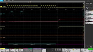
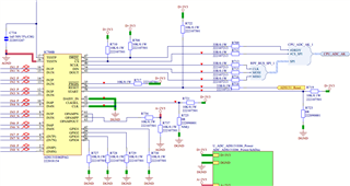
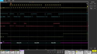
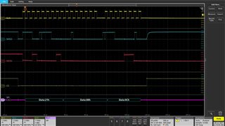
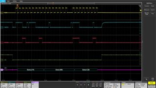
We have made hardware prototypes which has both ADS124S08 and ADS131E06 ADCs. I'm trying to read ADS131E06's CONFIG1 (01h) register after RESET line toggle. I'm getting 00h from MISO line. On the other side ADS124S08 works like charm. I'm able to run application code with ADS124S08. I'm sending first 2 bytes from microcontroller's firmware as 21h, 00h. Schematics & Scope captures attached.

Expected value is 91h. But, I'm getting 00h

  • Hello Sadashiva,

    Thank you for your post.

    Can you check for the /DRDY pulse after start-up? The period between consecutive /DRDY falling edges should match the default data rate of 32 kSPS. This will confirm that the device is functioning. You can also try reading back the ID register.

    If neither of these work, can you pulse the /RESET pin an extra time while supplies remain connected, then repeat the above suggestions?

    Regards,

    Ryan

  • Hi Ryan,

    We did few experiments past 2 days  -

    I'm running same firmware code for below mentioned Case-1 & Case-2.

    Similar code works perfectly with ADS124S08

    Case-1: START = LOW

    • MISO line is stable.
    • There is NO /DRDY pulse after start-up.
    • MISO data is always Zero. Scope capture is same which attached previously.
    • ADC's RESET is held for 10 sec and SPI access started after 10 sec after RESET removal. No changes

    Case-2: START = HIGH

    • MISO line is not stable. Toggles randomly. It looks to me very strange.
    • There is /DRDY pulse after start-up. /DRDY falling edges matches the default data rate of 32 kSPS
    • ADC's RESET is held for 10 sec and SPI access started after 10 sec after RESET removal. No changes

  • Hello Sadashiva,

    This makes sense - the START pin must be high (or you must send the START command) in order for the modulators to begin converting and for /DRDY to pulse at the data rate.

    Are you sending the SDATAC command before trying to read/write registers? The device defaults to RDATAC mode at start up.

    Regards,

    Ryan

  • Thanks Ryan, this helps..!

    It started working after I send SDATAC command. This was not needed for ADS124S08. Missed it some how.

    Case-1: START = LOW (NO /DRDY pulse after start-up) also working after this command.

    In our application, We're planning to operate in case-1.