This thread has been locked.

If you have a related question, please click the "Ask a related question" button in the top right corner. The newly created question will be automatically linked to this question.

ADS9120EVM-PDK: ADS9120EVM-PDK: How to connect directly to SPI Bus (instead of PHI Controller)

Part Number: ADS9120EVM-PDK
Other Parts Discussed in Thread: ADS9120

I need to directly connect the ADS9120EVM-PDK board to my PIC32MZ SPI bus.

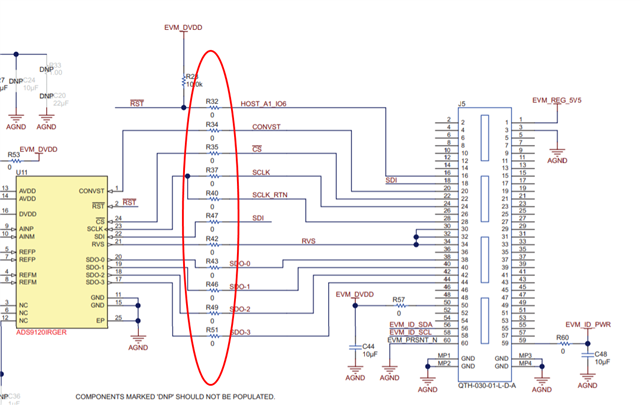
Q) What is the mating connector for J5?

Q) Can I connect my PIC32MZ to the SPI bus as a master on  the PHI Controller board?

  • Hello Ramin,

    The mating connector for J5 used on the PHI board is:

    QSH-030-01-L-D-A

    https://www.digikey.com/en/products/detail/samtec-inc/QSH-030-01-L-D-A/1106524

    If you want to connect the PIC32MZ, then remove and do not use the PHI board.  You can directly connect your host MCU to the ADS9120EVM board.  You can either do this through the mating connector, or most folks will solder wire jumpers onto the resistor pads R32...R51 that are in series with the IO lines.

    Regards,
    Keith Nicholas
    Precision ADC Applications

  • Sorry for my delay to reply or close this ticket as I was stuck in a transition from my GMAIL to my new company email.

    Thank you Keith, you clearly answered my question. However, NOW I have a follow-up question:

        Q: What is the best way to power the ADS9120EVM-PDK in the absence of the PHI controller?

              Should I provide 5.5V across TP1/TP2?

  • Hello Ramin,

    You will need two supply voltages provided from a lab bench supply.  Connect +5.5V between TP1 (LDO_IN_5V5) and TP2 (GND).  This supply provides power to the linear regulator, which powers the amplifiers and reference.  You will also need to connect +1.8V between TP5 (EVM_DVDD) and TP2 (GND).  This power supply directly connects to the ADS9120, and must be well regulated (the absolute maximum voltage on this supply is 2.1V, any higher and the device could be damaged).  Do not 'hot connect' the 1.8V supply to this pin.

    Regards,
    Keith

  • Using ADS9120EVM "without" PHI is for firmware development. The analog range can be reduced.

    Can I use a +5V supply instead of +5.5V, and derive the +1.8V from it?

    Or, better yet, where on PHI can I tap into the +5.5V and +1.8V?

  • Hi Ramin,

    You should be able to use the PHI to power the ADS9120EVM and connect an external MCU if you remove the 0ohm resistors in the IO lines.

    I suggest removing R32, R34, R35, R37, R40, and R47 since these are outputs from the PHI FPGA.  You can then connect your external MCU to the PCB pads for these resistors at the same time the PHI is connected to the ADS9120EVM board.

    On power-up, the PHI will read the information from the EEPROM and set the proper voltages for both the +5.5V and +1.8V supplies.  As long as the digital outputs from the PHI are isolated from the ADC digital inputs by removing the above resistors, you should be able to get it to work.

    If using an external 5V supply, you can derive the +1.8V supply using a separate linear regulator.  In order to use the PHI supplies, it must read the EEPROM since it enables the power supplies and sets the voltage levels based on the EEPROM information.

    Regards,
    Keith