This thread has been locked.

If you have a related question, please click the "Ask a related question" button in the top right corner. The newly created question will be automatically linked to this question.

ADS1261: AC Excitation Frequency and Sample Rate-SPS

Part Number: ADS1261

Dear Support Team

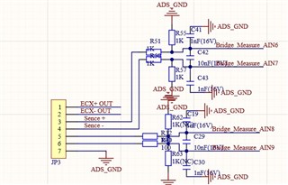
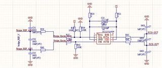
We are implementing AC excitation with ADS1261 for full bridge sensor measurement and met some issues during development

1. In data Sheet 9.4.3,the AC-excitation mode changes the nominal data rate, I want to know whether the data rate changed by configuring AC excitation is the same as the data rate sampled by me,what's the relationship between sampling rate and AC-excitation frequency?

2.. When I set the data rate to 40KSPS, the frequency is 2.5KHz. I wonder if the AC excitation frequency can continue to increase (I use the internal clock). My design target is AC frequencye:5Khz / voltage 6V, sampling rate> 10k SPS

3. I noticed that when my configured data rate is higher than 7200SPS, I can only use digital filter 5. The data I collected is unstable. I want to know what methods can be used to improve the stability in hardware and software configuration.

4. on the hardware, pull up-> delay-> pull down-> collect data. is this delay time related to the size of the data I collected?

  • Hi Wu,

    I think I am a bit confused what you mean by "AC excitation frequency"? There is no AC signal being applied to the bridge, the ADS1261's GPIOs are meant to control external switches that swap the bridge polarity. In some sense I guess this is like a applying a square wave to the bridge, but in a practical sense there is no real "AC excitation frequency" being applied to the bridge since AC excitation typically refers to a sinewave.

    The latency for the first conversion in AC excitation mode is described in section 9.4.2 (Chop Mode) in the ADC datasheet. As the datasheet says:"Referring to Table 8, the new data rate is equal to 1 / latency values and the first conversion latency is 2 × latency values" So, if you look at Table 8 and selected a data rate of 1200 SPS and a sinc 3 filter, you will see that the normal first conversion latency is 2.925 ms. In AC excitation mode, this value is doubled, or 5.85ms. Therefore, if you were using AC excitation mode at 1200 SPS and a sinc 3 filter, the first conversion would be available in 5.85ms (assuming no additional delays were applied). This is approximately equal to 170 SPS. Due to the operation of the device described in Section 9.4.2, second and subsequent conversion data on the same channel would be available at the values given in Table 8.

    Given this information, your comment about the 40kSPS data rate makes sense: according to Table 8, the first conversion latency is 0.179ms. For AC excitation mode, this is 2*0.179 or 0.358ms. This translates to ~2.8kSPS. So the ADC is operating as it should, and this is realistically the fastest the ADC can operate in AC excitation mode. Increasing the data rate will also increase the noise, especially at 40 kSPS.

    For data rates >7.2kSPS, the data by default passes through the sinc 5 filter. This is shown in Figure 60. As stated previously, running the ADC faster also increases the noise because the ADC oversamples less. This is probably the instability you are seeing, and is a direct result of sampling very fast.

    I am not sure what this sequence is supposed to be describing, can you please clarify?

    pull up-> delay-> pull down-> collect data

    The ADS1261EVM has the AC excitation feature built in, have you tried evaluating the EVM to get a better understanding of how the AC excitation feature works?

    -Bryan

  • Hi Bryan,

    Much Thanks for your quick reply. 

    What I don't fully understand is how to control the change rate of external switch of ads1261 AC bridge polarity and the maximum value of this switch rate that i can implement for my design.

    Pull up - > delay - > pull down - > collect data. What I want to express is the ADC of ads data conversion pin_ The delay time between high and low start.

    Thank a lot

    Regards

    Wu Jingqi

  • Hi Wu,

    The AC excitation timing is shown in Figure 7 in the ADC datasheet. This figure shows that the AC excitation period is given by t(ACX), which is 2*tSTDR (minimum). The times for tSTDR are given in Table 8, and are just the ADC data rate. So you can see that the AC excitation period is tied to the data rate you choose.

    You might also check out this document for more information about AC excitation mode: https://www.ti.com/lit/an/sbaa290a/sbaa290a.pdf

    -Bryan

  • Dear Bryan

    Thanks fort the feedback

    According to the table, the Max AC excitation period is 2.5Khz and the related SPS is 40K SPS. which will lead to getting noise for the Full fridge Output acquisition.  My initial target for this design-5khz / 10K SPS seems to be difficult to realize with ADA1261.

    Which AC excitation period and SPS can you recommend for the full bridge weight sensor in ADS1261 with high speed and high precision data acquisition?

    Much Thanks!

    Wu Jingqi

  • Hi Wu,

    What is the target noise performance for your application?

    You can check out the videos in our ADC noise series to help understand how to set a noise target for your system: https://training.ti.com/adc-noise?context=1139747-1140267-1128375-1140017

    -Bryan