Hello ,i have a question about ADS8168.
I use ADS8168 on my own design board.
I have test spi communication with ADS8168.
write_cmd(ADCCMD_WR_REG, 0xFF, 0x55);
write_cmd(ADCCMD_RD_REG, 0xFF, 0x0);
Iwrite data 0x55 on address 0xFF, and i read address 0xFF, it come out with data 0x55;
write_cmd(ADCCMD_WR_REG, 0xFFFF, 0x66);
write_cmd(ADCCMD_RD_REG, 0xFFFF, 0x0);
Iwrite data 0x66 on address 0xFF, and i read address 0xFF, it come out with data 0x66;
So I think the spi communication is ok .
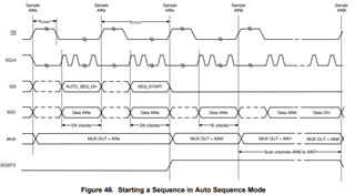
the i init ADS8168 and work in auto mode.
// enable writing
write_cmd(ADCCMD_WR_REG, REG_ACCESS, REG_ACCESS_BITS);
//write_cmd(ADCCMD_RD_REG, REG_ACCESS, 0x0);
// Powerup all except the ref/2 buffer
write_cmd(ADCCMD_WR_REG, REG_PD_CNTL, PD_CNTL_PD_REFby2);
// Data type: ADC value + 4-bit channel id
write_cmd(ADCCMD_WR_REG, REG_DATA_CNTL, DATA_CNTL_FORMAT_CHID);
// Vref = 4V096
write_cmd(ADCCMD_WR_REG, REG_OFST_CAL, OFST_CAL_4V096);//REG_SDO_CNTL4
write_cmd(ADCCMD_WR_REG, REG_SDO_CNTL4, SDO_CNTL4_SEQSTS_CFG);
write_cmd(ADCCMD_WR_REG, REG_SEQ_START, SEQ_START_START);
while(readpin(SEQSTS)!=0)
{
chanel2=readChannelCustom();
chanel6=readChannelCustom();
}
the readchannelcustom fun follow
uint16_t readChannelCustom()
{
//Establish time
for(int i=0;i<50000;i++);
unsigned char tx_data[2]={0,0};
unsigned char rx_data[2]={0,0};
XSpi_Transfer(&SpiInstance, tx_data, rx_data, 2);
return rx_data[0] << 8 | rx_data[1];
}
when i change input voltage from 0.4-2.0 in channel 0 , it outcome data 0x8e1.
so which step is wrong ?