This thread has been locked.

If you have a related question, please click the "Ask a related question" button in the top right corner. The newly created question will be automatically linked to this question.

ADS1220: Problem using DRDY on Power Up to detect A2D is operational

Part Number: ADS1220
Other Parts Discussed in Thread: TPS22810

This is an issue that came up a few years ago, where the DRDY was not asserted due to the Internal Clock not starting properly:

https://e2e.ti.com/support/data-converters/f/73/t/550358?ADS1120-DRDY-pin-not-going-low-after-Power-up

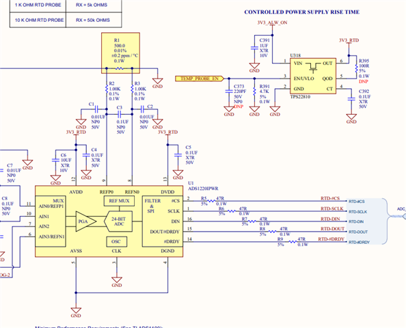
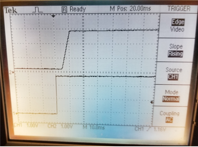
The recommended solution is to implement a Controlled Rise Time on the A2D power supply. We implemented a special Rise Time Controlled Switch, and the number of problem occurrences appeared to be significantly reduced. Due to the Pandemic, we did not visit our Contract Manufacturer. Not all customers use the A2D (for Temperature Measurement). Recently, we did find our CM was having problems, and Field Problems were being reported.

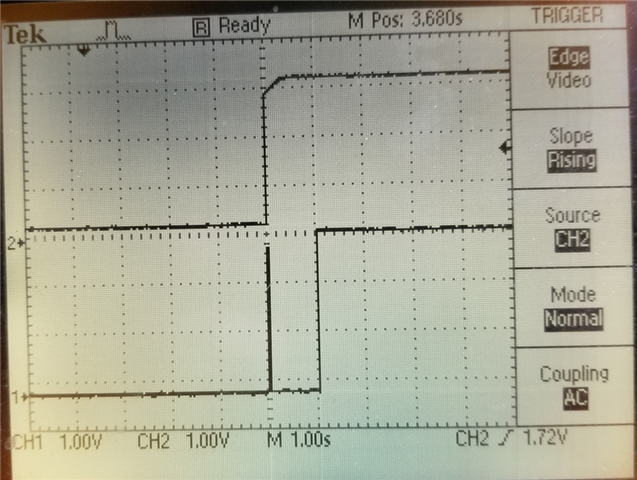
Our product switches on the Controlled Rise Time Power to the A2D, and then after a delay, checks that the DRDY is asserted (POR on A2D causes a one time conversion). If we do not see the DRDY asserted, we deem this a failure. Knowing that an external event such as a single clock on the SPI CLK will clear the asserted DRDY, I would ask if there is another method to confirm the A2D is actually properly operating (with internal clock operating normally). Most of our Field Returns are due to this issue!!

Thank You,

Paul Masanek

Liquid Controls

  • Hi Paul,

    The ramp rate issue is specific to the DVDD supply.  What ramp rate are you currently using with the switch?  Do you have any scope shots showing the ramp rate at the DVDD device pin of the ADS1220?

    If you are polling DRDY, then yes an extraneous SCLK may mask that the device is operational.  If you use a falling edge interrupt on DRDY, then you should be able to detect the transition.  How long is the delay between power-up and checking the state on DRDY?  Are you using CS to frame your communication or are you holding CS low?

    If CS is held or tied low, and if the device does actually startup and an extraneous SCLK(s) is transmitted, you should be able to read registers or conversion data following an extra delay to ensure SPI timeout has occurred.  The SPI timeout is approximately another 55ms.

    If you are seeing this on multiple devices, or with a specific CM run, then I would suspect that there is still a ramp rate issue on DVDD.

    Best regards,

    Bob B

  • Hi Bob,

    Attached is a snip of the schematic. According to the TPS22810 data sheet, I should see a rise time of 550 uS. I will verify. As I understand, the internal clock issue is more predominant at temperature extremes. I have a gut feeling that the internal oscillator is operating, but we are failing this simple DRDY test. That is why I am looking for an alternate method to verify the ADS1220 is functioning properly.

    Thanks,

    Paul Masanek

  • Hi Paul,

    Thanks for the information.  If you have a specific board that is causing you issues, please verify the ramp time.  The most critical period is from 0 to about 1.6V.  the ramp should be monotonic.  The startup issue can be made worse at higher temps, but the issue was first discovered at room temperature.

    Best regards,

    Bob B

  • Hi Bob,

    Attached is a capture of the power up ramp. The bottom trace is the enable to the switch, the top the voltage at the ADS1220. You will see a monotonic ramp of 5mS duration. Yet, this unit is failing our DRDY test. Again, I suspect that enabling the SPI or some other event is clearing the ADS1220 DRDY. I believe this unit is likely working. This is why I am asking for an alternate method to determine the A2D is functioning.

    Paul

  • Hi Paul,

    Thanks for the scope plot.  Although the level of detail is small the slope trend appears to be correct.  Have you tried to monitor and trigger on DRDY to check if a pulse ever takes place?  

    I see that the supply for both AVDD and DVDD come from the same source.  Have you verified that the AVDD voltage is available at the device pin (just in case there may be some manufacturing issue of the PCB)?  I would also verify that there are no solder issues at the supply, ground pins and CLK pin.

    Both AVDD and DVDD must be available for the device to come out of the power-up reset (POR).  If the device is released from the reset state, the internal oscillator will start.  After a period of time the internal oscillator will stabilize.  After a period of several clock cycles the device is released for SPI communication.  Once the SPI has been released the communication can start and does not require the internal oscillator any longer.

    I would suggest that if DRDY is not seen to have a falling edge, that the RESET command be transmitted to the ADS1220.  Following the RESET command and wait period for reset completion attempt to write and read registers as shown in the pseudo code section 9.1.6 of the datasheet.

    Best regards,

    Bob B

  • Hi Bob,

    Attached is a trace capture showing the Power to the A2D, the DRDY being asserted, and then DRDY being cleared 1 second later. The mystery is, why is it being cleared. Does sending the RESET command to the ADS1220 cause a capture and subsequent DRDY? This could be used if we fail the test initially.

    Paul

  • Hi Paul,

    It is does appear that following release from POR the device is working and initiates the correct behavior on startup.  A glitch on the SPI SCLK will force the DRDY high.  As I really know nothing about what is going on with the startup of your system or your code I can't say what might be happening one second after power is applied to the ADS1220.

    If the SPI pins from the micro initiate in an unknown state, it is possible that the pins can glitch.  The best method for prevention of a glitch causing an issue is to have a pullup on the CS pin which will lock out any glitch.

    As to issuing the RESET command, the device will reset to initial configuration but I am unsure if this will trigger a conversion.  Unfortunately I cannot verify this today, but I can tell you that if you write to a register, the device will start a single conversion.  I assume that you have to write a configuration at some point so this may be another option if you just want to monitor DRDY.

    I really don't know what to tell you at this point.  If the device is operational as indicated in the scope shot shown above, you should be able to communicate with the device.  I have offered several options and now you just need to pick one.

    Best regards,

    Bob B