This thread has been locked.

If you have a related question, please click the "Ask a related question" button in the top right corner. The newly created question will be automatically linked to this question.

AMC3306M25: diag pin triggering

Part Number: AMC3306M25

Hello,

I have three of these devices configured as per your datasheet with a clk input of 5 to 5.6MHz and a VDD of 3.4V. (I tried increasing the clock frequency from 5 to 5.6 MHz to ensure being at the low end of the data sheet value was not causing this issue)
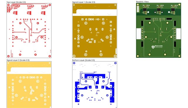
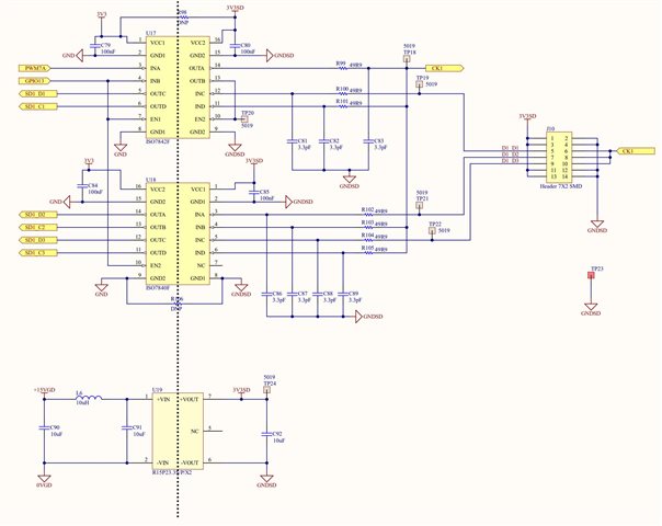
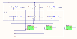
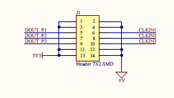
My circuit is: 

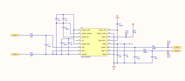
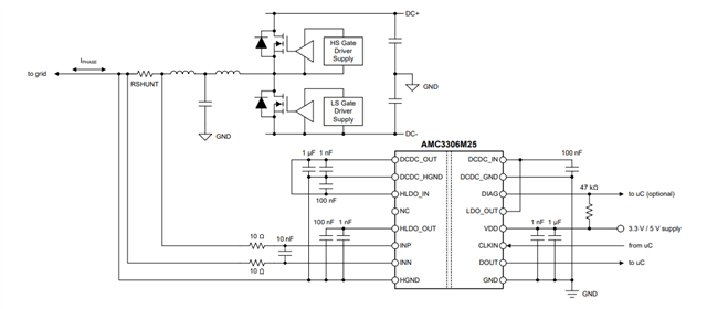
Which is copied from the datasheet and is in a circuit similar to the one shown in the datasheet, but currently operating with no High voltage circuits operational.

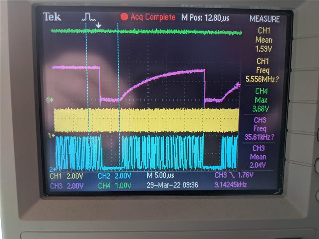
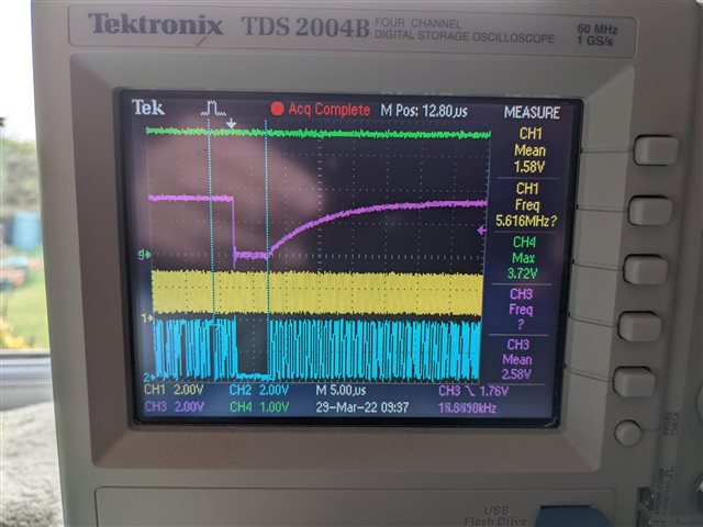
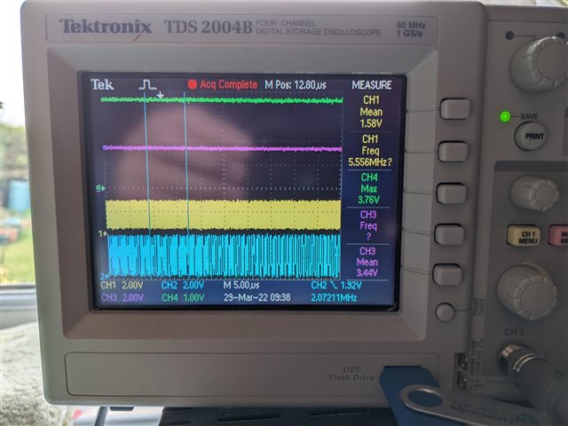
For some reason, one of the three is working just fine and sending a steady pulse stream which can be read by the microprocessor, the other two are  periodically triggering the diag pin and sending a stream of zeros every now and again. This seems to be every few seconds as captured below:

top trace is the diag pin, middle is the clk signal  and bottom is the data.

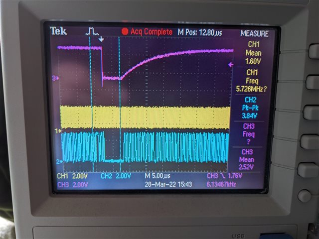
So, according to the datasheet this suggests there is some issue with the high side dc/dc circuit on these two devices. 

Assuming my circuit components are as per the above diagram, this would seem to suggest two out of the three devices may be faulty?  Are there any other conditions or do you have any suggestions as to what might be causing the this Diag pin to be sporadically triggered?  Or is it just a case of swapping out the devices?

regards

Steve

  • Hi Steve,

    Is it possible to share the layout? Gerbers would be fine. If you are uncomfortable sending publicly, you can always send a friend request and you can share it privately. It seems unlikely that both devices would be faulty and I would first like to determine if there could be any potential causes. However, just as a sanity check, you can replace on the 'bad' devices with a known good one to see if the behavior persists. 

    Additionally, have you probed the DCDC out pin? If you can add a probe so we can monitor the status of the DCDC out when the DIAG pin goes low, that would be helpful. 

    Regards,
    Aaron Estrada

  • Hi Aaron,

    Ok. so carried out the measurements as requested. N.B my scope and differential probe not that accurate so we should compare the relative differences in the traces:

    Faulty lane 1 - DCDC out on green

    Faulty lane 2 - DCDC out on green

    healthy lane 3 - DCDC out on green

    using a DVM the following readings were taken:

    lane 1 HLDOout - 3.2009 DCDCout - 3.49

    lane 2 HLDOout - 3.2129 DCDCout - 3.49

    lane 3 HLDOout - 3.2054 DCDCout - 3.527

    So there is a difference between the healthy lane and the faulty lanes.

    PCB layouts:

    The local layout to each chip is pretty much identical. The working one is the one farthest away from the ribbon connector.

    There is a ribbon cable (10cm long) between this power interface PCB and the control PCB at the control PCB end the following circuit is driving the interface:

    Note the local power for the external side of the SDFM interface is from a RECOM 15V/3V3 DC/DC converter.

    I note on your evaluation board you have an additional 10uF capacitor on the 3V3 supply and ours is local to the 15V/3V3 DC/DC converter. Should we consider beefing up the capacitance at the remote end?

    Any other ideas?

    I note these chips are out of stock at the moment so we are going to be a bit stuck if the conclusion is that we have two faulty ones.

    regards

    Steve

  • Aaron,

    Ok so I just moved my scope ground from TP23 on the control board to a local ground on the power interface as I was going to take a look at the remote 3V3 to the devices. All three sensors seem have started working the same now.  A rather unexpected finding, but worth reporting as it may shed some light on the issue...

    However, if I remove the scope entirely, the indications from the microprocessor is suggesting all three are still working ok.

    Now, I just put the scope ground back on TP23 and it has continued to work on all three channels.  So this may be a red herring or perhaps something is temperature sensitive or..... 

    Dropped my clock frequency back to 5MHz and it is still stable on all three....

    Any thoughts?

    regards

    steve

  • Hi Steve,

    This is very interesting. So to confirm, you have everything working as intended? Regarding the bypass caps on the 3.3V supply, I would like to confirm if you have capacitors close to the VDD pin of the AMC. If they are only on the source side, then that may be a little concerning. We recommend that bypass capacitors be placed as close to the device pins as possible. 

    I will review the information you presented in greater detail and get back to you shortly. 

    Regards,

    Aaron Estrada

  • Hi Aaron,

    All the decoupling caps are close to the devices as per the reccomendations in the datasheet. Yes it started running ok after an hour or so and continued to do so for several hours.

    I guess if i start it up again tomorrow and it fails initially we might suspect temperature or some such.

    Regards

    Steve

  • Hi Steve, 

    That is interesting. Perhaps there could have been a grounding issue and when you initially added the probe, it somehow shifted something the right way and resolved it. Taking a deeper look, I would also like to know where you got the parts from. Do you have the name of the manufacturer? If you can send over the markings on the top of the IC for all 3 parts, that would be great. We can also take a look to check some information on the devices. 

    Additionally, I am trying to understand how things are routed on the PCB of the photos you sent. Do you have a full schematic for the board with the AMC's on it? I am trying to see what these diodes and large caps are used for. 

    Regards,

    Aaron Estrada

  • Aaron,

    the overall circuit is just a three-phase bridge with the three devices as previously provided. They are connected to the main control board via the header shown:

    We have two of these boards built and I briefly ran both yesterday for a few minutes and both seemed to be working ok. (The data in the microprocessor was stable for all three channels on both boards).  I probably need to do a longer test to satisfy myself they are both operating without any glitches.

    I can't quite imagine why attaching a scope ground to the supply ground should make a difference to two of the devices and not the third, that's very odd....

    The devices were all bought from Mouser I believe, probably about a year ago when they still could be found in the world...

  • Hi Steve,

    Thanks for the details and I agree. I am quite stumped on why the probe ground could have changed things. I guess this is sort of a red herring case right now that all devices are working properly. Moving forward, I would just double check all of your ground connections to ensure they are solid as well as double check that the common mode voltage specification isn't being violated either. 

    You also noted above that you had two boards built. If you see the issue come back and it's only on 1 board, then I would try and swap the suspect parts with good parts from the working board to see if there is still an issue. You can then place the suspect parts on the good board and check if it's functioning correctly. This is something we call an ABA swap and gives us information on whether the behavior follows the part or the board. Unfortunately, that seems like the only advice I can give right now. I will close the thread unless you have any more questions. If you see the issue come back, simply reply to this post and it will open it back up. 

    Best Regards,
    Aaron Estrada