Other Parts Discussed in Thread: ADS124S08
Hello,
I shorted the JP1 on the ASD124S08 EVM https://www.ti.com/tool/ADS124S08EVM so that it could be controlled with another microcontroller to develop a linux driver and I am not able to read or write the registers.
See below setup:
Microcontroller: nrf5340-dk
RTOS: Zephyr
SDK : nrf SDK V1.8.0
SPI Clock: 5MHz
When attempting to read back all registers. I get all zeros.
To test the spi read register operation I have a single infinite while loop to read the Data Rate register.
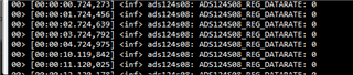
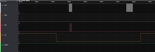
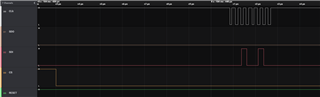
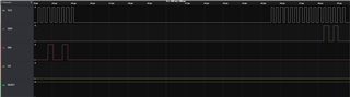
Below is the resulting wave form:
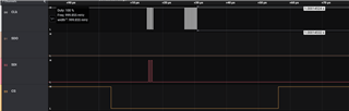
As shown above, it doesnt appear that the register is being read at all after issuing the RREAD command.
See below source code for my driver please refer to macros in the bottom of ads124s08.c and the spi implementation within ads124s08_spi.c:
ads124s08.c
#define DT_DRV_COMPAT ti_ads124s08
#include <init.h>
#include <sys/byteorder.h>
#include <sys/__assert.h>
#include <logging/log.h>
LOG_MODULE_REGISTER(ads124s08, CONFIG_SENSOR_LOG_LEVEL);
#include "ads124s08.h"
#include <devicetree.h>
#include <drivers/gpio.h>
#include <nrf.h>
#include <hal/nrf_gpio.h>
static const struct device *dev_start;
static const struct device *dev_reset;
// configure GPIO Pins for CS, Start and reset
static void init_gpio(void) {
int status;
dev_reset = device_get_binding(ADS124S08_RESET_LABEL);
if (dev_reset == NULL){
LOG_ERR("dev_reset device_get_binding() failure.");
return;
}
status = gpio_pin_configure(dev_reset, ADS124S08_RESET_PIN, GPIO_OUTPUT_ACTIVE);
if (status < 0){
LOG_ERR("dev_reset gpio_pin_configure() failure.");
return;
}
dev_start= device_get_binding(ADS124S08_START_LABEL);
if (dev_start == NULL){
LOG_ERR("dev_start device_get_binding() failure.");
return;
}
status = gpio_pin_configure(dev_start, ADS124S08_START_PIN, GPIO_OUTPUT_ACTIVE);
if (status < 0){
LOG_ERR("dev_start gpio_pin_configure() failure.");
return;
}
#ifndef CONFIG_ADS124S08_TRIGGER
nrf_gpio_cfg_input(DRDY_PIN, NRF_GPIO_PIN_PULLUP);
#endif
}
static void ads124s08_set_start_pin(int STATE){
gpio_pin_set(dev_start, ADS124S08_START_PIN, STATE);
}
static void ads124s08_set_reset_pin(int STATE){
gpio_pin_set(dev_reset, ADS124S08_RESET_PIN, STATE);
}
static const struct sensor_driver_api ads124s08_driver_api = {
// .attr_set = ads124s08_attr_set,
#if CONFIG_ADS124S08_TRIGGER
.trigger_set = ads124s08_trigger_set,
#endif
// .sample_fetch = ads124s08_sample_fetch,
// .channel_get = ads124s08_channel_get,
};
static int ads124s08_reset(const struct device *dev){
#if ENABLE_SOFT_CONFIGS // software reset
struct ads124s08_data *ads124s08 = dev->data;
ctrl = ADS124S08_CMD_RESET;
ads124s08_spi_cmd_send(dev, ctrl);
#else // hardware reset
ads124s08_set_reset_pin(HIGH);
k_sleep(K_MSEC(100));
ads124s08_set_reset_pin(LOW);
k_sleep(K_MSEC(100));
ads124s08_set_reset_pin(HIGH);
k_sleep(K_MSEC(100));
#endif
return 0;
}
static int ads124s08_init(const struct device *dev)
{
struct ads124s08_data *ads124s08 = dev->data;
const struct ads124s08_config *cfg = dev->config;
int status;
ads124s08->bus = device_get_binding(cfg->bus_name);
if (!ads124s08->bus) {
LOG_ERR("master not found: %s", cfg->bus_name);
return -EINVAL;
}
cfg->bus_init(dev);
init_gpio();
//Reset Device
status = ads124s08_reset(dev);
uint8_t reg;
while (1){
status = ads124s08->hw_tf->read_reg(dev,ADS124S08_REG_DATARATE, ® );
LOG_INF("ADS124S08_REG_DATARATE: %x", reg);
k_sleep(K_MSEC(1000));
}
if (status < 0){
LOG_ERR("ads124s08_init(). Unable to read status register");
}
return 0;
}
#if DT_NUM_INST_STATUS_OKAY(DT_DRV_COMPAT) == 0
#warning "ADS124S08 driver enabled without any devices"
#endif
/*
* Device creation macro, shared by ADS124S08_DEFINE_SPI() and
*/
#define ADS124S08_DEVICE_INIT(inst) \
DEVICE_DT_INST_DEFINE(inst, \
ads124s08_init, \
NULL, \
&ads124s08_data_##inst, \
&ads124s08_config_##inst, \
POST_KERNEL, \
CONFIG_SENSOR_INIT_PRIORITY, \
&ads124s08_driver_api);
#define IS_LSM303AGR_DEV(inst) \
DT_NODE_HAS_COMPAT(DT_DRV_INST(inst), st_lsm303agr_accel)
#define DISC_PULL_UP(inst) \
DT_INST_PROP(inst, disconnect_sdo_sa0_pull_up)
/*
* Instantiation macros used when a device is on a SPI bus.
*/
#define ADS124S08_HAS_CS(inst) DT_INST_SPI_DEV_HAS_CS_GPIOS(inst)
#define ADS124S08_DATA_SPI_CS(inst) \
{ .cs_ctrl = { \
.gpio_pin = DT_INST_SPI_DEV_CS_GPIOS_PIN(inst), \
.gpio_dt_flags = DT_INST_SPI_DEV_CS_GPIOS_FLAGS(inst), \
}, \
}
#define ADS124S08_DATA_SPI(inst) \
COND_CODE_1(ADS124S08_HAS_CS(inst), \
(ADS124S08_DATA_SPI_CS(inst)), \
({}))
#define ADS124S08_SPI_CS_PTR(inst) \
COND_CODE_1(ADS124S08_HAS_CS(inst), \
(&(ads124s08_data_##inst.cs_ctrl)), \
(NULL))
#define ADS124S08_SPI_CS_LABEL(inst) \
COND_CODE_1(ADS124S08_HAS_CS(inst), \
(DT_INST_SPI_DEV_CS_GPIOS_LABEL(inst)), (NULL))
#define ADS124S08_SPI_CFG(inst) \
(&(struct ads124s08_spi_cfg) { \
.spi_conf = { \
.frequency = \
DT_INST_PROP(inst, spi_max_frequency), \
.operation = (SPI_WORD_SET(8) | \
SPI_OP_MODE_MASTER | \
SPI_MODE_CPOL | \
SPI_MODE_CPHA), \
.slave = DT_INST_REG_ADDR(inst), \
.cs = ADS124S08_SPI_CS_PTR(inst), \
}, \
.cs_gpios_label = ADS124S08_SPI_CS_LABEL(inst), \
})
#ifdef CONFIG_ADS124S08_TRIGGER
#define GPIO_DT_SPEC_INST_GET_BY_IDX_COND(id, prop, idx) \
COND_CODE_1(DT_INST_PROP_HAS_IDX(id, prop, idx), \
(GPIO_DT_SPEC_INST_GET_BY_IDX(id, prop, idx)), \
({.port = NULL, .pin = 0, .dt_flags = 0}))
#else
#define ADS124S08_CFG_INT(inst)
#endif /* CONFIG_ADS124S08_TRIGGER */
#define ADS124S08_CONFIG_SPI(inst) \
{ \
.bus_name = DT_INST_BUS_LABEL(inst), \
.bus_init = ads124s08_spi_init, \
.bus_cfg = { .spi_cfg = ADS124S08_SPI_CFG(inst) }, \
ADS124S08_CFG_INT(inst) \
}
#define ADS124S08_DEFINE_SPI(inst) \
static struct ads124s08_data ads124s08_data_##inst = \
ADS124S08_DATA_SPI(inst); \
static const struct ads124s08_config ads124s08_config_##inst = \
ADS124S08_CONFIG_SPI(inst); \
ADS124S08_DEVICE_INIT(inst)
/*
* Main instantiation macro. Use of COND_CODE_1() selects the right
* bus-specific macro at preprocessor time.
*/
#define ADS124S08_DEFINE(inst) \
COND_CODE_1(DT_INST_ON_BUS(inst, spi), \
(ADS124S08_DEFINE_SPI(inst)), \
)
DT_INST_FOREACH_STATUS_OKAY(ADS124S08_DEFINE)
ADS124s08_SPI.c
/*
 *
 * Datasheet:
 * https://www.ti.com/product/ADS124S08
 */

#define DT_DRV_COMPAT ti_ads124s08

#include <string.h>
#include "ads124s08.h"
#include <logging/log.h>
#include <hal\nrf_gpio.h>


#if DT_ANY_INST_ON_BUS_STATUS_OKAY(spi)

LOG_MODULE_DECLARE(ads124s08, CONFIG_SENSOR_LOG_LEVEL);

/* ADS124S08 supports only SPI mode 0, word size 8 bits, MSB first */
#define ADS124S08_SPI_CFG			SPI_WORD_SET(8)


static int ads124s08_spi_write(const struct device *dev,uint8_t value, uint8_t len)
{
	struct ads124s08_data *data = dev->data;
	const struct ads124s08_config *cfg = dev->config;
	const struct spi_config *spi_cfg = &cfg->bus_cfg.spi_cfg->spi_conf;

	const struct spi_buf tx_buf = {
			.buf = &value,
			.len = 1,
	};
	const struct spi_buf_set tx = {
		.buffers = &tx_buf,
		.count = 1
	};

	if (len > 64) {
		return -EIO;
	}


	nrf_gpio_pin_clear(data->cs_ctrl.gpio_pin);

	if (spi_write(data->bus, spi_cfg, &tx)) {
		return -EIO;
	}

	nrf_gpio_pin_set(data->cs_ctrl.gpio_pin);

	return 0;
}


static int ads124s08_spi_read(const struct device *dev,uint8_t *value, uint8_t len)
{
	struct ads124s08_data *data = dev->data;
	const struct ads124s08_config *cfg = dev->config;
	const struct spi_config *spi_cfg = &cfg->bus_cfg.spi_cfg->spi_conf;


	uint8_t buffer_tx[1] = {ADS124S08_CMD_NOP};

	const struct spi_buf tx_buf = {
			.buf = buffer_tx,
			.len = 1,
	};
	const struct spi_buf_set tx = {
		.buffers = &tx_buf,
		.count = 1
	};
	const struct spi_buf rx_buf[2] = {
		{
			.buf = NULL,
			.len = 2,
		},
		{
			.buf = value,
			.len = len,
		}
	};
	const struct spi_buf_set rx = {
		.buffers = rx_buf,
		.count = 2
	};


	if (len > 64) {
		return -EIO;
	}

	if (len > 1) {
		buffer_tx[0] |= 0x0;
	}

	nrf_gpio_pin_clear(data->cs_ctrl.gpio_pin);

	if (spi_transceive(data->bus, spi_cfg, &tx, &rx)) {
		return -EIO;
	}
	nrf_gpio_pin_set(data->cs_ctrl.gpio_pin);

	return 0;
}


static int ads124s08_reg_read(const struct device *dev, uint8_t reg_addr,
			    uint8_t *pRxData)
{
	struct ads124s08_data *data = dev->data;
	const struct ads124s08_config *cfg = dev->config;
	const struct spi_config *spi_cfg = &cfg->bus_cfg.spi_cfg->spi_conf;
	const uint8_t len = 2; // read back 4 bytes from reg


	uint8_t buffer_tx[3];
	buffer_tx[0] = ((ADS124S08_START_REG_MASK & reg_addr )  | ADS124S08_CMD_RREG);
	buffer_tx[1] = 0x00; //number of registers to read minus 1
	buffer_tx[2] = 0x00 ; // no op


	const struct spi_buf tx_buf = {
			.buf = buffer_tx,
			.len = 3,
	};
	const struct spi_buf_set tx = {
		.buffers = &tx_buf,
		.count = 1
	};
	const struct spi_buf rx_buf[2] = {
		{
			.buf = NULL,
			.len = 1,
		},
		{
			.buf = pRxData,
			.len = len,
		}
	};
	const struct spi_buf_set rx = {
		.buffers = rx_buf,
		.count = 2
	};


	if (len > 64) {
		return -EIO;
	}

	if (len > 1) {
		buffer_tx[0] |= 0x0;

	}


	nrf_gpio_pin_clear(data->cs_ctrl.gpio_pin);

	if (spi_transceive(data->bus, spi_cfg, &tx, &rx)) {
		return -EIO;
	}

	nrf_gpio_pin_set(data->cs_ctrl.gpio_pin);

	return 0;
}

static int ads124s08_reg_write(const struct device *dev, uint8_t reg_addr,
			     uint8_t *value, uint8_t len)
{
	struct ads124s08_data *data = dev->data;
	const struct ads124s08_config *cfg = dev->config;
	const struct spi_config *spi_cfg = &cfg->bus_cfg.spi_cfg->spi_conf;
	uint8_t buffer_tx[2] = { ( reg_addr & ADS124S08_START_REG_MASK) | ADS124S08_CMD_WREG , 0};
	const struct spi_buf tx_buf[2] = {
		{
			.buf = buffer_tx,
			.len = 2,
		},
		{
			.buf = value,
			.len = len,
		}
	};
	const struct spi_buf_set tx = {
		.buffers = tx_buf,
		.count = 1
	};


	if (len > 64) {
		return -EIO;
	}

	// if (len > 1) {
	// 	buffer_tx[0] |= ADS124S08_SPI_AUTOINC;
	// }

	if (spi_write(data->bus, spi_cfg, &tx)) {
		return -EIO;
	}

	return 0;
}


static int adsd124s08_read_sample(const struct device *dev, uint8_t *value, uint8_t len){
	return ads124s08_spi_read(dev,value,len);
}

static int adsd124s08_write_command(const struct device *dev, uint8_t value){
	return ads124s08_spi_write(dev,value,1);
}

static int ads124s08_spi_read_reg(const struct device *dev, uint8_t reg_addr,
				uint8_t *value)
{
	return ads124s08_reg_read(dev, reg_addr, value);

}

static int ads124s08_spi_write_reg(const struct device *dev, uint8_t reg_addr,
				uint8_t value)
{
	uint8_t tmp_val = value;

	return ads124s08_reg_write(dev, reg_addr, &tmp_val, 1);
}


static const struct ads124s08_transfer_function ads124s08_spi_transfer_fn = {
	.read_reg  = ads124s08_spi_read_reg,
	.write_reg  = ads124s08_spi_write_reg,
	.read_samp = adsd124s08_read_sample,
	.write_command = adsd124s08_write_command,
};

int ads124s08_spi_init(const struct device *dev)
{
	struct ads124s08_data *data = dev->data;
	const struct ads124s08_config *cfg = dev->config;
	const struct ads124s08_spi_cfg *spi_cfg = cfg->bus_cfg.spi_cfg;

	data->hw_tf = &ads124s08_spi_transfer_fn;

	if (spi_cfg->cs_gpios_label != NULL) {

		/* handle SPI CS thru GPIO if it is the case */
		data->cs_ctrl.gpio_dev =
			    device_get_binding(spi_cfg->cs_gpios_label);
		if (!data->cs_ctrl.gpio_dev) {
			LOG_ERR("Unable to get GPIO SPI CS device");
			return -ENODEV;
		}

		LOG_ERR("SPI GPIO CS configured on %s:%u",
			spi_cfg->cs_gpios_label, data->cs_ctrl.gpio_pin);
	}

	return 0;
}
#endif /* DT_ANY_INST_ON_BUS_STATUS_OKAY(spi) */
ads124s08.h
#ifndef ZEPHYR_DRIVERS_SENSOR_ADS124S08_ADS124S08_H_
#define ZEPHYR_DRIVERS_SENSOR_ADS124S08_ADS124S08_H_


#include <kernel.h>
#include <device.h>
#include <sys/util.h>
#include <stdint.h>
#include <drivers/gpio.h>
#include <drivers/sensor.h>
#include <string.h>


#if DT_ANY_INST_ON_BUS_STATUS_OKAY(spi)
#include <drivers/spi.h>
#endif


#define DEBUG_MODE (1)
#if(DEBUG_MODE)
	#define DEBUG_PRINT printk
#else
	#define DEBUG_PRINT(...)
#endif

#define HIGH (0xFF)
#define LOW  (0x00)


#define MULTI_CHANNEL_READ (0) // read through every channel

#define ENABLE_SOFT_CONFIGS (0)

// #define SINGLE_SHOT_MODE

#if defined(SINGLE_SHOT_MODE)
	#define SINGLE_SHOT_MODE_BIT (0x20)
#else
	#define SINGLE_SHOT_MODE_BIT (0x00)
#endif
// GPIO Pins

// #define ADS124S08_CS_LABEL	      DT_GPIO_LABEL(DT_ALIAS(gpiocus0), gpios)
// #define ADS124S08_CS_PIN	      DT_GPIO_PIN(DT_ALIAS(gpiocus0), gpios)
#define ADS124S08_RESET_LABEL 	  DT_GPIO_LABEL(DT_ALIAS(gpiocus1), gpios)
#define ADS124S08_RESET_PIN	      DT_GPIO_PIN(DT_ALIAS(gpiocus1), gpios)
#define ADS124S08_START_LABEL     DT_GPIO_LABEL(DT_ALIAS(gpiocus2), gpios)
#define ADS124S08_START_PIN	      DT_GPIO_PIN(DT_ALIAS(gpiocus2), gpios)


// Interrupt Pins
#if DT_INST_PROP_HAS_IDX(0, irq_gpios, 1)
/* INT1 is configured */
#define ADS124S08_INT1_GPIOS_PIN		DT_INST_GPIO_PIN_BY_IDX(0, irq_gpios, 0)
#define ADS124S08_INT1_GPIOS_FLAGS		DT_INST_GPIO_FLAGS_BY_IDX(0, irq_gpios, 0)
#define ADS124S08_INT1_GPIO_DEV_NAME	DT_INST_GPIO_LABEL_BY_IDX(0, irq_gpios, 0)
#else

#define ADS124S08_INT1_GPIOS_PIN		DT_INST_GPIO_PIN(0, irq_gpios)
#define ADS124S08_INT1_GPIOS_FLAGS		DT_INST_GPIO_FLAGS(0, irq_gpios)
#define ADS124S08_INT1_GPIO_DEV_NAME	DT_INST_GPIO_LABEL(0, irq_gpios)

#endif


#define DRDY_PIN (43)

#define RES (double)((double)VREF/pow(2,23))

// Commands

#define ADS124S08_CMD_NOP	0x00
#define ADS124S08_CMD_WAKEUP	0x02
#define ADS124S08_CMD_PWRDWN	0x04
#define ADS124S08_CMD_RESET	0x06
#define ADS124S08_CMD_START	0x08
#define ADS124S08_CMD_STOP	0x0A
#define ADS124S08_CMD_SYOCAL	0x16
#define ADS124S08_CMD_SYGCAL	0x17
#define ADS124S08_CMD_SFOCAL	0x19
#define ADS124S08_CMD_RDATA	0x12
#define ADS124S08_CMD_RREG	0x20
#define ADS124S08_CMD_WREG	0x40

// Registers

#define ADS124S08_REG_ID 0x00
#define ADS124S08_REG_STATUS 0x01
#define ADS124S08_REG_INPMUX 0x02
#define ADS124S08_REG_PGA 0x03
#define ADS124S08_REG_DATARATE 0x04
#define ADS124S08_REG_REF 0x05
#define ADS124S08_REG_IDACMAG 0x06
#define ADS124S08_REG_IDACMUX 0x07
#define ADS124S08_REG_VBIAS 0x08
#define ADS124S08_REG_SYS 0x09
#define ADS124S08_REG_OFCAL0 0x0A
#define ADS124S08_REG_OFCAL1 0x0B
#define ADS124S08_REG_OFCAL2 0x0C
#define ADS124S08_REG_FSCAL0 0x0D
#define ADS124S08_REG_FSCAL1 0x0E
#define ADS124S08_REG_FSCAL2 0x0F
#define ADS124S08_REG_GPIODAT 0x10
#define ADS124S08_REG_GPIOCON 0x11


/* ADS124S0x common channels */
#define ADS124S08_AIN0		0x00
#define ADS124S08_AIN1		0x01
#define ADS124S08_AIN2		0x02
#define ADS124S08_AIN3		0x03
#define ADS124S08_AIN4		0x04
#define ADS124S08_AIN5		0x05
#define ADS124S08_AINCOM	0x0c
#define ADS124S08_AIN6		0x06
#define ADS124S08_AIN7		0x07
#define ADS124S08_AIN8		0x08
#define ADS124S08_AIN9		0x09
#define ADS124S08_AIN10		0x0a
#define ADS124S08_AIN11		0x0b
#define ADS124S08_MAX_CHANNELS	12

#define ADS124S08_POS_MUX_SHIFT	0x04
#define ADS124S08_INT_REF		0x09

#define ADS124S08_START_REG_MASK	0x1f
#define ADS124S08_NUM_BYTES_MASK	0x1f

#define ADS124S08_START_CONV	0x01
#define ADS124S08_STOP_CONV	0x00


#define ADS124S08_CHIP_ID 0x00

#if DT_ANY_INST_ON_BUS_STATUS_OKAY(spi)
struct ads124s08_spi_cfg {
	struct spi_config spi_conf;
	const char *cs_gpios_label;
};
#endif /* DT_ANY_INST_ON_BUS_STATUS_OKAY(spi) */

union ads124s08_bus_cfg {

#if DT_ANY_INST_ON_BUS_STATUS_OKAY(spi)
	const struct ads124s08_spi_cfg *spi_cfg;
#endif /* DT_ANY_INST_ON_BUS_STATUS_OKAY(spi) */
};

struct ads124s08_config {
	const char *bus_name;
	int (*bus_init)(const struct device *dev);
	const union ads124s08_bus_cfg bus_cfg;
};

struct ads124s08_transfer_function {
	int (*read_reg)(const struct device *dev, uint8_t reg_addr,
			uint8_t *value);
	int (*write_reg)(const struct device *dev, uint8_t reg_addr,
			 uint8_t value);
	int (*read_samp)(const struct device *dev, uint8_t *value, uint8_t len);
	int (*write_command)(const struct device *dev, uint8_t value);

};


union asd124s08_sample{
	uint8_t bytes[3];
	uint32_t raw[1];
};

struct ads124s08_data {
	const struct device *bus;
	const struct ads124s08_transfer_function *hw_tf;
	union asd124s08_sample sample;
	uint8_t tempRecordings[18]; // 3 bytes per sample * 6 channels = 18 bytes

#ifdef CONFIG_ADS124S08_TRIGGER
	const struct device *dev;
	const struct device *gpio_int1;
	struct gpio_callback gpio_int1_cb;

	sensor_trigger_handler_t handler_drdy;
	atomic_t trig_flags;
	enum sensor_channel chan_drdy;

#if defined(CONFIG_ADS124S08_TRIGGER_OWN_THREAD)
	K_KERNEL_STACK_MEMBER(thread_stack, CONFIG_ADS124S08_THREAD_STACK_SIZE);
	struct k_thread thread;
	struct k_sem gpio_sem;
#elif defined(CONFIG_ADS124S08_TRIGGER_GLOBAL_THREAD)
	struct k_work work;
#endif

#endif /* CONFIG_ADS124S08_TRIGGER */

#if DT_ANY_INST_ON_BUS_STATUS_OKAY(spi)
	struct spi_cs_control cs_ctrl;
#endif /* DT_ANY_INST_ON_BUS_STATUS_OKAY(spi) */
};


#ifdef CONFIG_ADS124S08_TRIGGER
int ads124s08_trigger_set(const struct device *dev,
		       const struct sensor_trigger *trig,
		       sensor_trigger_handler_t handler);

int ads124s08_init_interrupt(const struct device *dev);

#endif

int ads124s08_spi_init(const struct device *dev);

#endif
overlay file:
/*
 * Copyright (c) 2019 Nordic Semiconductor ASA
 *
 * SPDX-License-Identifier: Apache-2.0
 */

 &spi2 {
	compatible = "nordic,nrf-spim";
	status = "okay";
	sck-pin = <47>;
	mosi-pin = <45>;
	miso-pin = <46>;
	cs-gpios = <&gpio1 12 GPIO_ACTIVE_LOW>;

	ads124s08@0 {
		compatible = "ti,ads124s08";
		label = "ADS124S08";
		spi-max-frequency = <5000000>;
		reg = <0>;
		irq-gpios = <&gpio1 11 GPIO_ACTIVE_LOW>;

	};
};


&uart0 {
	status = "okay";
	current-speed = <115200>;
	tx-pin = <20>;
	rx-pin = <22>;
	rts-pin = <19>;
	cts-pin = <21>;
};

/ {
    gpiocustom {
        compatible = "gpio-keys";
        // gpiocus0: gpiocus_0 {
        //     gpios = <&gpio1 12 GPIO_ACTIVE_LOW>;
        //     label = "CS";
        // };
        gpiocus1: gpiocus_1 {
            gpios = <&gpio1 10 GPIO_ACTIVE_LOW>;
            label = "RESET";
        };

		gpiocus2: gpiocus_2 {
            gpios = <&gpio0 27 GPIO_ACTIVE_HIGH>;
            label = "START";
        };
    };
    aliases {
        // gpiocus0 = &gpiocus0;
        gpiocus1 = &gpiocus1;
		gpiocus2 = &gpiocus2;

    };
};
Any help would be appreciated.
Thank you,
Matt