This thread has been locked.

If you have a related question, please click the "Ask a related question" button in the top right corner. The newly created question will be automatically linked to this question.

DAC161S997: DAC161S997 Self-Powered with DS8500 HART modem

Part Number: DAC161S997

Hi,

We have a self-powered DAC161S997 design connected to DS8500 HART modem. We facing problem we think it has with FSK-out filtering.

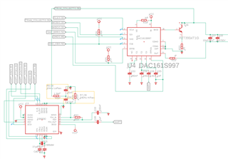
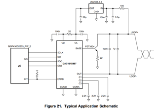
I'm being confused between the DAC161S997 datasheet and the dac161s997evm schematic regarding the HART and C1, C2, C3.

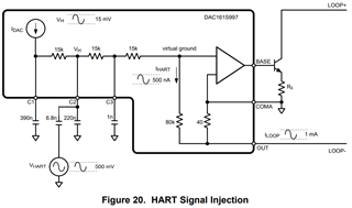
And even the AC decoupling capacitor to C2. I can find deffirent values in the datasheet. What values are recumended for HART?

In DS8500 it is recumended to have a decouplig capacitor on the FSK_out anything greater than 20nF. But you have 6.8nF.

In our design we used c1,c2,c3 390nF, 220nF, 1nF respectevly. and even the 6.8nF capacitor and a 1uF capacitor on the FSK_out as you can see in the schematic.

Now we have issue that the HART communication does not working and we receive incorrect messages or data.

We tried to remove the 6.8nF capacitor and get same result.

One more confusing thing in the dac161s997evm schematic is that the HART_RX & HART_TX. Are they jumpers or connectors?

Bacause pin 2 in these are connectet together. And is R11 needed for HART

Thanks in advance

  • Ahmad,

    For the DAC161S997, the different values are meant for changing the frequency response of the current control. While some tests were run with C1, C2, C3 = 2.2nF, the values in Figure 20 are used for HART responses. I believe that's what is used on the EVM.

    For the HART communication, have you looked at the AC signal with a scope? The TX of the HART chip connects to the HART_TX1 header and the RX connects to the HART_RX1 header. For the communication, are you just getting bad data? or is there just no response?

    I did notice the following old E2E post about the DAC161S997EVM and HART operation. I thought this had been addressed previously and correct, so I'll need time to check this out. It explains that C1 and C3 might have been swapped on the board.

    https://e2e.ti.com/support/data-converters-group/data-converters/f/data-converters-forum/370848/dac161s997evm-and-hart-signaling


    Joseph Wu

  • Hi Joseph,

    Thank you for replying and helping us with this case.

    We getting bad data. There is response. We checked the sine wave with oscilloscope and can verify that the frequency and amplitude are fine.

    We are not using the EVM right now. We are comparing our design with datasheet and EVM schematic.

  • Ahmad,


    In the previous post, I mentioned the swap of C1 and C3 on the EVM. I did check and it looks like the EVM user's guide was corrected in 2014, so that is not the problem.

    I looked at your schematic and I didn't see anything wrong with the DAC161S997 side. However, I'm not very familiar with the DS8500, but nothing seems aout of place.

    For your HART communications, what sort of bad data are you getting? Are you getting some bad bits in the datastream? Are you missing sections of the data where you drop the first or last bytes of transmission? Do you have problems in transmit or receive? Have you checked the FSK against the D_IN/D_OUT and the RTS/OCD?


    Joseph Wu

  • Hi Joseph,

    We receive bad data and shorter data

    For example instead of 

     FF FF FF FF 06 80 00 0E 00 05 FE >FB< FB 05 05 00 01 08 00 00 00 01 [7B]

    We get 

    FF FF 06 00 08 05 FB BF 50 >>>00<<< 40 08 00 01 [EF]

    Ex2.

    instead of 

    FF FF FF FF 86 BB FB 00 00 01 0D >17< 00 05 14 C1 54 50 18 04 12 D4 C5 48 91 53 80 D3 CE 25 43 D2 01 01 >>7A<< [CF]

    We get

    FF FF 86 B7 00 01 43 11 05 >51< 54 85 04 22 5D 48 64 2A D3 AE 1A 49 01 40 AF [FE]

  • Ahmad,


    I still need a little clarification about the data path. Is this data being sent from the DS8500 to the DAC161S997 and then being received by another modem? Or is this data just being received by the DS8500 while the DAC161S997. I'm just trying to see if this is possibly a problem with the DS8500 and why you might have ruled that out.

    Regardless, have you tried to look at the FSK and correlated it with the digital output? It looks like this read sequence is missing several bits at a time, and I'd like to see if the FSK is being corrupted. Can you plot several bytes of this with an oscilloscope. You can look at it at the FSK_OUT of the DS8500. If there's a load resistor on the loop, you should also look at that.


    Joseph Wu