This thread has been locked.

If you have a related question, please click the "Ask a related question" button in the top right corner. The newly created question will be automatically linked to this question.

ADS8688A: ADS8688 disturb

Part Number: ADS8688A
Other Parts Discussed in Thread: ADS8688, ADS8688EVM-PDK

facing problem when using ads8688, there are common mode noises on the AGND, may affected digital system, how to solve it?
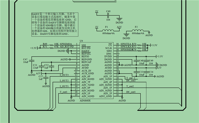
when control DO to drive the contactor, the analog system is affected, FPGA can not get sample properly

can i reset 8688 using rst/pd pin everytime when sampling?  8688 internal registers may be altered by the disturbance?

  • Hi nirvana,

    Please see my suggestions below:

    • Do not use a ferrite bead between AGND and DGND. Using a single dedicated ground plane for both all AGND and DGND is strongly encouraged. For temporary test purpose, a 0ohm resistor can be used and this resistor should be placed as close to the ADC as possible. Again, a solid ground plane is recommended in your final design.
    •  A ferrite bead can not guarantee a clean power supply for AVDD. You can use a dedicated/low noise LDO to generate a clean supply source for AVDD in your feature design.
    • Connect AUX_GND to the AGND ground plane, and also short AUX_IN to the AGND plane if the AUX channel is not used.
    • This kind of reset is not recommended but you can.
    • It's possible as long as the data on the SDI match the register write operation format.

    Regards,

    Dale

  • aux channel is not used, the not connected pin will affect ads8688?

  • Hi nirvana,

    The AUX channel is connected to the multiplexer and share the same ADC with other channel. It's a good practice to short them to the AGND especially for AUX_GND pin in case they pick up noise.

    Regards,

    Dale

  • can i use internal register to disable aux channel?

  • Hi nirvana,

    The AUX channel can not be disabled, however it can only be selected in Manual mode. This should not be the direct reason to cause the issue, but it's a good practice to short them to the AGND especially for AUX_GND pin.

    Regards,

    Dale

  • i shorted AIN_xP pin with AGND, there were still disturbance on the samples. did the digial part of ADC affect by the electric pulse?

  • Hi nirvana,

    Have you looked into my 1st and 2nd suggestions above?

    Best regards,

    Dale

  • i have handled 1st and 2nd suggestions, some of my problems solved. but through the test, i think the digital part may be affected by the noise. the CS or the RST pin may be not stable.

  • the agnd and dgnd have been divided into two part, i think this might be the problem

  • does ADS8688EVM-PDK suite offer PCB files?

  • Hi nirvana,

    Splitting ground in your case is my biggest concern because the current loop may be much longer if the ground is not properly split. Our EVM  boards usually use a solid ground plane for all AGND and DGND, below is a common layer design for our EVM boards.

    • 1st layer (Top layer):  signal
    • 2nd layer(inner layer): GND - whole layer for all AGND and DGND
    • 3rd layer(inner layer):  power
    • 4th layer(Bottom layer):  signal.

    The ADS8688EVM has less requirements for power supplies and the circuity on the EVM is simple so both 2nd and 3rd inner layers were used for GND when this board was designed.

    Regards,

    Dale 

  •  we use 0 ohm resistor instead of ferrite bead, but it still not work. the ditial part of the system affected by outter noise. i have checked TIDA00170, the control system(mcu or FPGA or other things) is isolated with analog part, so the DGND and AGND of 8688 connected to form a GND plane for this. my question is how to connect ADC DGND to system DGND, is there any consideration?

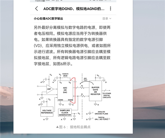
  • this is a app note demo, as shown in the pic, ADC GNDs are connected together, but how can ADC connect to host system?

  • Hi nirvana,

    We recommend to use a solid ground plane for all AGND and DGND pins of the ADC. A 0hm resistor can not be used to replace a solid ground plane because it depends where the resistor is, how you split the ground and also how the analog components and digital components are placed and designed on your pcb layout.

    The TIDA00170 shows a typical design when an isolation with digital isolator is required. All ground connections on the isolation side including ADS8688'S AGND/DGND and DAC's ground are sharing a same ground plane.

    When an isolation is not required, the ground plane of ADC can be a same ground plane of host controller. However, all analog components including the ADC should not be placed close to the digital circuit including the host controller. Also, a clean and low noise power supply is requested for AVDD of the ADC.

    Regards,

    Dale