This thread has been locked.

If you have a related question, please click the "Ask a related question" button in the top right corner. The newly created question will be automatically linked to this question.

DAC161S997: Status register readback issue

Part Number: DAC161S997

Hi..

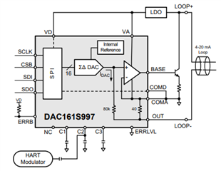
One of my customer is using DAC161S997 for their Industrial product where they are controlling the motor speed using 4 to 20mA input.

They are using 24V as Loop power supply for 4 to 20mA output & they also use 3.3V as external power & this 3.3V is not taken from the loop supply.

In above case, when 24V is not present  they are not able to get the fault status on EERB pin and also through status register. 

Also want to know if 24V connection is not present (consider wire break condition), will it show any loop error status either through ERRB or Error status register?

Need help, what could be the issue?

Mitesh

  • Hi Mitesh,

    Joe will take a look at this when he is back in office, July 5th.  The delay is due to the US holiday.

    Thanks,

    Paul

  • Joe,

    Any update from your side?

    Mitesh

  • Mitesh,


    The ERRB should be triggered when the loop is lost. The DAC sets an output current to drive the 80kΩ resistor to a set voltage below GND. This is matched across the 40Ω resistor. The BASE drives the transistor to set the feedback of the amplifier and the loop current. Most of the loop current comes through the 40Ω resistor.

    Because the loop current is set by the current through OUT it should be below GND. If the loop is broken, OUT should have no current, which should trigger the ERRB. Is there anything connected to OUT and what is the voltage of OUT relative to GND?

    In the setup are VD and VA shared? I wanted to check to see if it was possible that the entire analog section was shut down while leaving the digital powered. If the current sense is implemented purely in the analog section, I'm not sure what signal is fed back to the digital section. When the loop is broken, are they able to read any of the registers of the device just to check communications? In particular, ERR_CONFIG and STATUS may be useful to read.

    Can you post a schematic of this board? Because the device has a separate supply, it would be useful to find out how the device is connected to VD and VA power.


    Joseph Wu

  • Hi Joseph,

    Sorry for late reply. VD and VA are at same potential. And both are powered with 3.3VDC. 

    Alok Kakatkar

  • Alok,

    When there is no loop power, what happens to the BASE voltage and OUT voltage? I'd like to know more about how the device is reacting to the missing loop power, and how it's resolving the loop regulation.

    Note that I'm out of the office Thursday and Friday. It may take some time for me to respond back. 

    Joseph Wu