This thread has been locked.

If you have a related question, please click the "Ask a related question" button in the top right corner. The newly created question will be automatically linked to this question.

ADS8900BEVM-PDK: Serial resistors at the opamps outputs

Part Number: ADS8900BEVM-PDK
Other Parts Discussed in Thread: THS4551

Hi,

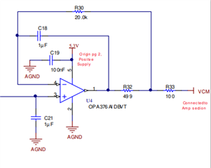
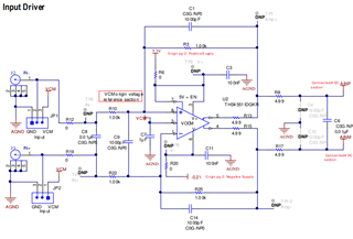
Just a question, why do you add serial resistors (R13, R15 and R32) at the opamps outputs to the ADS8900BEVM-PDK ?

Is there a document that describe this ?

Thanks

David

  • Hello David,

    R32, in addition to R30 and C18, is part of a frequency compensation network that allows the amplifier to drive a large capacitive load on VCM.  You can find details regarding this approach in TI Precision Labs: Op-Amps, section 10.6, Isolation resistor.

    https://training.ti.com/ti-precision-labs-op-amps-stability-isolation-resistor
    https://training.ti.com/sites/default/files/docs/opamps-stability-isolation-resistor-presentation-quiz.pdf

    R13 and R15 are used to reduce ringing on the amplifier output pins caused by the switched capacitor input of the ADC.  This in turn reduces the overall settling time. 

    Ideally, for best settling time, the internal output impedance of the amplifier should be purely resistive, but many amplifiers, including THS4551, have a complex output impedance with multiple poles and zeros in the response.  This complex impedance tends to increase the ringing (both magnitude and duration) on the outputs when the ADC input sampling capacitor is switched to the ADC input pins during the acquisition phase.  Adding these resistors to the amplifier output pins will help approximate a purely resistive output impedance, which is helpful to reduce the total settling time.

    I am not aware of a good application note that describes this approach in more detail, but this is a trick that we have used to improve overall settling time, which results in faster sampling rates and a higher effective resolution.  If interested, we do have good training material that shows how to choose an input amplifier, along with the input RC filter values (R8, R17, C6 on the EVM).  

    You can find details regarding this approach in TI Precision Labs: ADCs, section 8, SAR ADC input drive design.
    https://training.ti.com/ti-precision-labs-adcs-introduction-sar-adc-front-end-component-selection?context=1139747-1140267-1128375-1139106-1128643

    Regards,
    Keith Nicholas
    Precision ADC Applications