This thread has been locked.

If you have a related question, please click the "Ask a related question" button in the top right corner. The newly created question will be automatically linked to this question.

ADS1198ECGFE-PDK: Data converters forum

Part Number: ADS1198ECGFE-PDK
Other Parts Discussed in Thread: ADS1198

Hi,

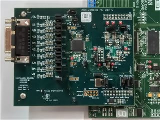
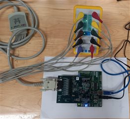
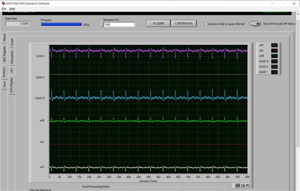
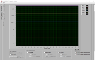
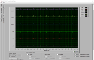
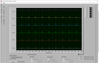
I am working on ADS 1198 ECG FE development board. I have interfaced ADS 1198 with Arduino. I am providing AVDD and DVDD for the board through Arduino. Here are my SPI connections for ADS1198 with Arduino SPI_MISO, SPI_MOSI, SPI_SCLK, SPI_CS, DRDY, RESET.

Is there any connections that I missed out to collect ECG data from the board?

Thanks in advance,

Shiva Ram

  • Hi Shiva,

    May I ask some questions?

    So, are you not using the MMB0 mother board that comes with the ADS1198 EVM board, correct?

    Have you tried using the ADS1198 with MMB0 mother board and the GUI to get familiar and test whether it functions properly or not?

    It's highly recommended to take pictures and note down the default jumpers settings/configuration for future reference and reset.

    When you provide AVDD, DVDD, AVSS and Vref from Arduino, do your AVDD, DVDD, AVSS and Vref meet the requirement and limits in the ADS1198 datasheet page 2?

    Please make sure your Arduino board is capable of supplying the appropriate voltage and current within the limits. E.g. What are your AVDD, DVDD, AVSS and Vref? Are you supplying Unipolar or bipolar power supply?

    Do you want to draw or provide some schematic or pins assignments to show how you connect the ADS1198 EVM board to the Arduino board?

    "Is there any connections that I missed out to collect ECG data from the board?" Yes, there might be some jumpers that you need to change.

    E.g. Will you want to use the on-chip clock or the on-EVM board clock or provide your own clock? This requires different jumper and register settings.

    Make sure your Arduino's SPI_SCLK also meet the requirement in data sheet given the corresponding power supply settings.

    Thanks

  • Hi ChienChun Yang,

    Yes I have tried ADS1198 using MMB0 mother board and installed ADS1198 ECG_FE software provided by texas instruments. Here are my default jumper configurations on the ADS1198 ECG development board. I have also removed the jumper J13A and J13B on the MMB0 mother board.

    I have changed the channel input from Input short to Normal Electrode. ADC register settings are shown below.


    When I try to acquire data LL and V1 Leads are not detected. Lead off register status is shown below.

  • Here I am attaching the setup given by me and I have used Cardiosim III ECG simulator for data acquiring to the ADS1198 development board.

    In the ECG Analysis tab I am getting limb leads signals as shown below.

  • Hi,

    How were the LL and V1 connected? To a simulator?

    Do you use RLD? Sometimes RLD helps drive/stabilize voltage to improve the LEAD OFF detection sensitivity. 

    Also, Lead-Off Control Register allows the user to configure the threshold for the lead-off comparator.

    Thanks

  • So, it seems EVM works with the GUI.

    Then, come back my comments to the post at begging -

    When you provide AVDD, DVDD, AVSS and Vref from Arduino, do your AVDD, DVDD, AVSS and Vref meet the requirement and limits in the ADS1198 datasheet page 2?

    Please make sure your Arduino board is capable of supplying the appropriate voltage and current within the limits. E.g. What are your AVDD, DVDD, AVSS and Vref? Are you supplying Unipolar or bipolar power supply?

    Do you want to draw or provide some schematic or pins assignments to show how you connect the ADS1198 EVM board to the Arduino board?

    I am assuming the Arduino you use have dedicated SPI pins, correct?

    "Is there any connections that I missed out to collect ECG data from the board?" Yes, there might be some jumpers that you need to change.

    E.g. Will you want to use the on-chip clock or the on-EVM board clock or provide your own clock? This requires different jumper and register settings.

    Make sure your Arduino's SPI_SCLK also meet the requirement in data sheet given the corresponding power supply settings.

  • Hi, 

    Yes, I have connected all the leads from simulator to J1 connector on the development board. If I removed the RLD connection from the simulator then it is not showing any signals in the ECG display tab.

    Thanks in advance,

  • Hi,

    Let me understand correctly. 

    Are you saying that with RLD connection, you can read signals correctly. And, without RLD connection, you cannot read signals.

    If so, that makes some sense as RLD helps drive the Unit(simulator or body) to be acquired/measured to a common mode voltage such that the Unit is not floating in an unknow voltage(too high or too low) that is out of the acquiring range with respect to the ADS1198's GND/AVSS.

    So, it's recommended to use RLD.

  • Hi, 

    When you provide AVDD, DVDD, AVSS and Vref from Arduino, do your AVDD, DVDD, AVSS and Vref meet the requirement and limits in the ADS1198 datasheet page 2?

    Yes, AVDD, DVDD, AVSS and Vref meets the absolute maximum ratings as per data sheet.

    Are you supplying Unipolar or bipolar power supply?

    I am supplying Unipolar power supply.

    Do you want to draw or provide some schematic or pins assignments to show how you connect the ADS1198 EVM board to the Arduino board?

    Sure, that would be a huge help for me.

    I am assuming the Arduino you use have dedicated SPI pins, correct?

    Yes, I am using the default SPI connections on the Arduino board.

    "Is there any connections that I missed out to collect ECG data from the board?" 

    I have provided internal clock oscillator or on-chip clock on the EVM board. For internal clock I have provided Jumper JP18 to 2-3 pins.

    CLKSEL pin in J3 connector is grounded with jumper JP23 to 1-2 pins.


    Thanks in advance

  • Here are my connections with arduino board

          ADS1198                                  Arduino

    J3.1 (SPI_CS)           ------------>     D10 pin

    J3.3 (SPI_SCK)         ------------>     D13 pin

    J3.8 (RESET)            ------------>     D5 pin

    J3.11 (SPI_IN)           ------------>     D11 pin

    J3.13 (SPI_OUT)       ------------>     D12 pin

    J3.15 (SPI_DRDY)    ------------>     D6 pin

  • Hi,

    Let's make sure you setup the master CLK correctly first -

    "

    "Is there any connections that I missed out to collect ECG data from the board?" 

    I have provided internal clock oscillator or on-chip clock on the EVM board. For internal clock I have provided Jumper JP18 to 2-3 pins.

    CLKSEL pin in J3 connector is grounded with jumper JP23 to 1-2 pins.

    "

    Are you using on-chip internal clock or not? Because if you install JP18 in 2-3 position, this actually uses the external OSC clock on the EVM board. So, please search JP18 in EVM user guide to make sure this is what your intention? Or, you want to uninstall JP18?

    Again and similar, Do you install JP23 in 1-2 or 2-3 or not installed? Please search JP23 in EVM user guide, e.g. page 36 to make sure you set the JP23 the way you want.

    For SPI -

    "

    I am assuming the Arduino you use have dedicated SPI pins, correct?

    Yes, I am using the default SPI connections on the Arduino board.

    "

    Comments: please make sure the SCLK meet the requirement stated in datasheet. And, feel free to take a look of the following thread related to SPI -

    https://e2e.ti.com/support/data-converters-group/data-converters/f/data-converters-forum/772490/faq-ads129x-what-are-the-correct-polarity-and-phase-cpol-cpha-spi-settings/2856911#2856911

    https://e2e.ti.com/support/data-converters-group/data-converters/f/data-converters-forum/775262/faq-ads129x-i-m-having-trouble-communicating-with-my-ads129x-device-via-spi-what-debug-steps-i-should-try/2868427#2868427

    Thanks

  • Hi,

    I had provided power supply to ADS1198 PDK with 6V battery. I am able to extract all the Chest leads but I am not able to display LEAD II and aVL leads. Is there any options that I need to change to display those signals on ADS 1198 ECG software?

    Thanks in advance,

  • Hi

    Have you changed any jumper settings or configuration on the EVM board when working the EVM board with the GUI? 

    And, are you still using the EVM's GUI with EVM? Or, is the EVM now connected to other host/Master or system?

    There are only 8 measured/measurable channels with respect to the EVM board setup per user guide page 52 and 53.

    Leads that are/cannot be measured by channels will have to be obtained through calculation from the measured leads per user guide page 32 section 4.6.

    Please follow user guide page 31 Section 4.4 show how to display the Limbs & Augmented Leads or Chest Leads by selecting the Plot Set Selection. Go to Analysis->ECG Display Tab, the bottom left corner.

    Please follow User guide page 25, section 3.5.4, Go to Analysis->ECG Display Tab, the bottom left corner to select Plot Set Selection.

    Can you show a complete/full screenshot of the Globally Set Channels tab/panel to see if Channel Input controls are set to Normal Electrode?

    And, a complete/full screenshot of the Analysis->ECG Display Tab.

    For other measurable channels, the following should show 8 measured/measurable channels with respect to the EVM board setup per user guide page 52 and 53.

    Go to Analysis->Scope Tab,  at the bottom right drop down box selection, you can select the channel and channel legend is showing at the right side of the plot.

    Go to Analysis->Histogram Tab, at the bottom right drop down box selection, you can select the channel and channel legend is showing at the right side of the plot.

    Thanks

  • Have you changed any jumper settings or configuration on the EVM board when working the EVM board with the GUI? 

    No, I didn't change any jumper settings on the EVM board.

    Are you still using the EVM's GUI with EVM? Or, is the EVM now connected to other host/Master or system?

    Yes, I am still working with EVM'S GUI i.e MMB0 board with EVM only. EVM is connected to MMB0 board only.

    Yes, I do understand that Lead III, aVR, aVL, aVF leads need to be derived using the formulae. But my question is that how can I obtain V1 and LL leads to be detected. With out LL lead I am not getting the correct output signals for Lead I, Lead II and Leads V1 to V6 as per user guide Page 32.

    Thanks,

  • By the way here I attach my Lead-Off status Registers

  • Hi,

    "But my question is that how can I obtain V1 and LL leads to be detected."

    First of all, there is No LL leads.  there are three primary LEADs work as differential, i.e. RA-LL, RA-LA and LA-LL. There is LL electrode, but not LL lead.


    Can you go to the About page/tag in the GUI and see if you can read the the Device ID. What is that?

    If you are using a ECG simulator, make sure the LL output is functional properly.

    Refer to EVM user guide page 52 schematic, can you check the good connectivity from J1 pin11 LL to the ECG LL on the EVM?

    Then, EVM user guide page 53 schematic, JP31~JP32, are in the default positions referring to page 37 Table 5.

    It's suggested to refer to EVM user guide page 6 and 7 to check and compare with the Default Jumper/Switch Config.

    In the GUI, Refer tot Page 11 in user guide, could you click Reset to Programmed Defaults?

    Refer to page 19, see if you can select the Channel # that is corresponding to the LEAD II(from the post, it's missing this, correct?), i.e. in the same Channel on the EVM board, where RA and LL signal line/trace go in.

    Refer to page 25, see if you can see the LEAD II.

    Thanks

  • Hi,

    Can you go to the About page/tag in the GUI and see if you can read the the Device ID. What is that?

    In the about tab it shows device ID as ADS1198 and firmware version as 0.2.2

    If you are using a ECG simulator, make sure the LL output is functional properly.

    Yes my ECG simulator is working fine.

    Refer to EVM user guide page 52 schematic, can you check the good connectivity from J1 pin11 LL to the ECG LL on the EVM?

    I had verified the connectivity for LL and V 1 electrodes from J 1 to ADS1198 ECG sensor. There is no issue in the connectivity.

    Then, EVM user guide page 53 schematic, JP31~JP32, are in the default positions referring to page 37 Table 5.

    It's suggested to refer to EVM user guide page 6 and 7 to check and compare with the Default Jumper/Switch Config.

    EVM has default jumper configurations as i mentioned in the screenshot above.

    In the GUI, Refer tot Page 11 in user guide, could you click Reset to Programmed Defaults? 

    I had reset the EVM module to programmed defaults as per your suggestion but no change in the status of LL and V 1 electrodes.

    Refer to page 19, see if you can select the Channel # that is corresponding to the LEAD II(from the post, it's missing this, correct?), i.e. in the same Channel on the EVM board, where RA and LL signal line/trace go in.

    In the scope analysis tab, My channels are displayed as shown below.

    Thanks

  • Hi,

    In your ECG simulator picture earlier, which ports represent the RA, LA, LL and RL electrodes? 

    Did you configure the ECG simulator to output the the 3 primary leads?

    • Lead I: RA (-) to LA (+) (Right Left, or lateral)
    • Lead II: RA (-) to LL (+) (Superior Inferior)
    • Lead III: LA (-) to LL (+) (Superior Inferior)

    I see you got Lead I and Lead III readings, but not Lead II in earlier screenshot picture.

    I see you got Lead aVR, aVF readings, but not aVL in earlier screenshot picture.

    And, if your Lead Off registers were setting correctly, then from your Lead Off status screen shot, it indicate that the electrodes connected to IN8P and IN3P are not connected well or fell off, could you please double check these two?

    Also, please check the signal source for the RA and LL electrode to make sure they are not the same, as from the equation above, if RA and LL are the same, then their differential signal(i.e. substract from each other) will be very low voltage close to 0.

    Can you increase the gain a little bit for the Channel that takes in Lead II, i.e. RA and LL.

    Can you show me a picture of your ECG simulator again and mark/identify which ports you connect to RA, LA, LL and RL?

    Please remove all other chest leads for now.

    Thanks.

    The following link is just useful for reference -

    https://litfl.com/ecg-limb-lead-reversal-ecg-library/

    Bipolar leads

    • Lead I is the voltage difference between the LA and RA electrodes (LA – RA), directed towards LA at zero degrees.
    • Lead II is the voltage difference between the LL and RA electrodes (LL – RA), directed towards LL at +60 degrees.
    • Lead III is the voltage difference between the LL and LA electrodes (LL – LA), directed towards LL at +120 degrees.
    Augmented Unipolar leads
    • Lead aVL is directed towards the LA electrode (-30 degrees), calculated as follows: aVL = LA – (RA + LL)/2.
    • Lead aVF is directed towards the LL electrode (+90 degrees), calculated as follows: aVF = LL – (LA + RA)/2.
    • Lead aVR is directed towards the RA electrode (-150 degrees), calculated as follows: aVR = RA – (LA + LL)/2.
  • Hi,

    I see you got Lead I and Lead III readings, but not Lead II in earlier screenshot picture.

    I see you got Lead aVR, aVF readings, but not aVL in earlier screenshot picture.

    And, if your Lead Off registers were setting correctly, then from your Lead Off status screen shot, it indicate that the electrodes connected to IN8P and IN3P are not connected well or fell off, could you please double check these two?

    Yes, I have cross checked the electrodes to the simulator, the electrodes are connected good.

    Can you increase the gain a little bit for the Channel that takes in Lead II, i.e. RA and LL.

    I had changed the Gain to 1,2,4,6,8 and 12. still it doesnot display any signal.

    Can you show me a picture of your ECG simulator again and mark/identify which ports you connect to RA, LA, LL and RL?

    Please remove all other chest leads for now.

    If I remove the chest leads it is not displaying anything. Here if I remove RL,LL and V6 electrodes it doesnot display any signal.

    If I removed V1 electrode from the SIMULATOR, in the lead_off STATUS REGISTER IN1P changes to red color which is connected to V6 electrode on the ADS1198 EVM module.

    If I removed V2 electrode from the SIMULATOR, in the lead_off STATUS REGISTER IN7P changes to red color which is connected to V5 electrode on the ADS1198 EVM module.

    If I removed V3 electrode from the SIMULATOR, in the lead_off STATUS REGISTER IN6P changes to red color which is connected to V4 electrode on the ADS1198 EVM module.

    If I removed V4 electrode from the SIMULATOR, in the lead_off STATUS REGISTER IN5P changes to red color which is connected to V3 electrode on the ADS1198 EVM module.

    If I removed V5 electrode from the SIMULATOR, in the lead_off STATUS REGISTER IN4P changes to red color which is connected to V2 electrode on the ADS1198 EVM module.

    If I removed V6 electrode from the SIMULATOR, IN8P  which is not detecting in the lead_off STATUS REGISTER  will be connected to V1 electrode on the ADS1198 EVM module.

    Here my electrodes RA, LA, LL are not detecting in the LEAD_OFF STATUS Register. 

    I am Using Cardiosim III ECG simulator.

  • In your ECG simulator picture earlier, which ports represent the RA, LA, LL and RL electrodes? Could you show me a picture and with marker/highlight each of the electrode port? And, connect RA, LA, LL and RL only. As from your earlier ECG simulator picture, I cannot see/tell which pins are RA, LA, LL and RL.

    Can you show me a picture of your ECG simulator again and mark/identify which ports you connect to RA, LA, LL and RL only?

    Make sure the cable between the electrode connector/button/buckle to the other terminal pins are good connectivity/conductivity.

    Also, could you try the following in EVM GUI, set the channel to

    internal Test Signal(CHnSET[2:0] = 101) for the channel you miss signal.

    Please follow user guide page 29

    4 ADS1x98ECG-FE Input Signals

    NOTE: Before evaluating specific ECG functions, it is recommended that the user acquire data with inputs shorted internally. This configuration ensures that the board is operating properly.

    4.1 Input Short Testing

    By default, the EVM powers up with the individual channels to an internal short with a data rate of 500SPS and a PGA gain of 6. Once the Acquire button is pressed, the Scope Analysis should reflect inputreferred VPP values less than 5µVPP

    4.2 Internal Test Signals Input

    Configuration Register 2 controls the signal amplitude and frequency of an internally-generated square wave test signal. The primary purpose of this test signal is to verify the functionality of the front-end MUX, the PGA, and the ADC. The test signals may be viewed on the ECG Display tab, as Figure 31 shows. Detailed instructions for using the ECG Display tab are provided in Section 3.5.4.

    Let me know if you can see the internal Test Signals.

  • Hi,

    In your ECG simulator picture earlier, which ports represent the RA, LA, LL and RL electrodes? Could you show me a picture and with marker/highlight each of the electrode port? And, connect RA, LA, LL and RL only. As from your earlier ECG simulator picture, I cannot see/tell which pins are RA, LA, LL and RL.

    Can you show me a picture of your ECG simulator again and mark/identify which ports you connect to RA, LA, LL and RL only?

    Sure, I am attaching my ECG simulator Electrodes in the figure shown below

    Make sure the cable between the electrode connector/button/buckle to the other terminal pins are good connectivity/conductivity.

    ECG simulator RA electrode is connected to both RA and LA electrodes but not with RL and LL electrodes on the ADS1198 board.

    ECG simulator LA electrode is connected to both RA and LA electrodes but not with RL and LL electrodes on the ADS1198 board.

    ECG simulator LL electrode is connected to RA electrode but not with LA, RL and LL electrodes on the ADS1198 board.

    ECG simulator RL electrode is connected to LA electrode but not with RA, RL and LL electrodes on the ADS1198 board.

    The above connectivity is obtained when V6 electrode is connected to the simulator.

    ECG simulator RA electrode is connected to LA electrode but not with RA, RL and LL electrodes on the ADS1198 board.

    ECG simulator LA electrode is connected to LA electrode but not with RA, RL and LL electrodes on the ADS1198 board.

    ECG simulator RL electrode is connected to LA electrode but not with RA, RL and LL electrodes on the ADS1198 board.

    ECG simulator LL electrode is not connected to LA, RA, RL and LL electrodes on the ADS1198 board.

    The above connectivity is obtained without V6 electrode connected to the simulator.

    Thanks,

  • Also, could you try the following in EVM GUI, set the channel to

    internal Test Signal(CHnSET[2:0] = 101) for the channel you miss signal.

    Please follow user guide page 29

    Yes I had tried the channel set to test signal and it is shown below

  • If I remove all the chest electrodes and connect only RA, LA, RL and LL electrodes my ECG display tab does not  display limb and augmented leads as shown in the figure below.

  • Hi,

    In the internal Test Signal screen shot you shared, did you enable the test signal for the channel for Lead III? It's weird that previously your Lead I, III show signals, but now only Lead I, II show signals. What was the gain setting for the channel that takes lead II and III?

    Also, from the ECG cable connection description you sent to me, I don't know why you want to connect that way.

    Can you connect  ECG simulator

    RA electrode to ECG_RA in EVM

    LA electrode to ECG_LA in EVM

    LL electrode to ECG_LL in EVM

    RL electrode to ECG_RL in EVM

    Could you also double check your ECG simulator's Primary Limb Leads(Electrodes) output ports and settings/functionality? Is there way to adjust the output signal amplitude?

    Do you have a different ECG simulator that you can try/test with?

    Thanks.

  • Hi, 

    I had detected the problem with my ECG cable. I designed the ECG cable as per the ADS1198 EVM module. Now all the 12-channels are displayed. Thanks for your support on ADS1198 EVM module. ADS1198 ECGFE EVM module output is shown below.

    Thanks,

  • Hi, 

    Coming to the ADS1198 AFE board interfacing with Arduino UNO I am able to display Lead 1 and Lead 2 signals. V1 to V6  leads are displaying with more noise. Is there a way to reduce noise and display my remaining Electrodes?

    Thanks,

  • Hi,

    Did you keep a good record/note of the good combinations of registers settings that gave you the good signal quality?

    Do you use the RLD drive?

    Noises could come from many factors depending on your hardware, electrodes connections, cables, power supplies, power supplies topology and environment, etc. Also, precordial leads/electrodes could tend to be smaller signals and noisier.

    You may first want to identify what kind of noises they are and what could be the sources of the noises first?

    Eventually, based on the findings and answers from above, you may want to to remove or improve or attenuate the noises sources. Or, will need to implement addition analog or digital filters.

    Thanks 

  • Hi,
    Since I did not hear back from you, I believe my suggestions answered your questions.
    I will close this post and if you have any pending questions, feel free to post them here or open a new thread.
    Thanks and have a great day!