Other Parts Discussed in Thread: ADS7951
Hi Expert,
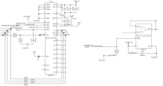
Customer is now using TI’s ADC sampling chip ADS7951. GPIO1 should be programmed as general purpose output (GPO) function.
The configuration process shows as following:
Step 1: The register are setting as the Table 11. The command is 0X4002.
0x4002 means:
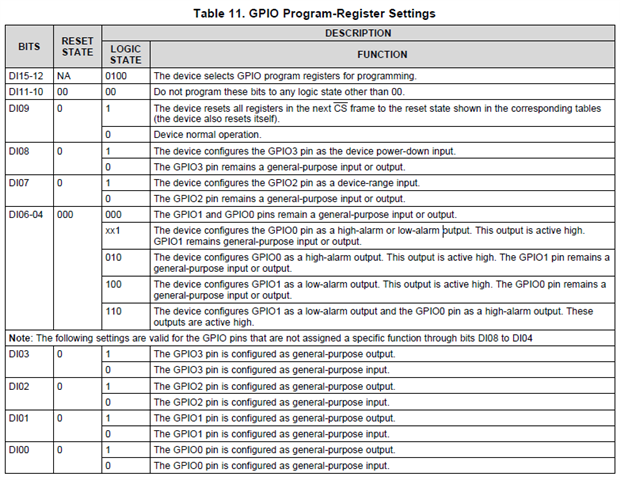
Bit 15-12 = 4 -> GPIO Pegister programming
Bit 11-10 = 0 -> OK (reserved)
Bit 9 = 0 -> Normal operation
Bit 8 = 0 -> GPIO3 is GPIO
Bit 7 = 0 -> GPIO2 is GPIO
Bit 6-4 = = -> GPIO1 and GPIO0 are GPIO
Bit 3 = 0 -> GPIO3 is an input
Bit 2 = 0 -> GPIO2 is an input
Bit 1 = 1 -> GPIO1 is an output
Bit 0 = 0 -> GPIO0 is an input
Step 2: Set Gpio1 to high
The register are setting as the Table 1. The command is 0X1812.
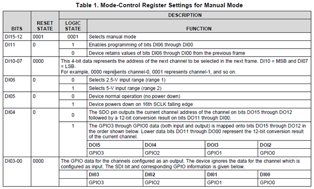
0x1812 means:
Bit 15-12 = 1 -> Manual Mode
Bit 11 = 1 -> Programming of Bits 0-6 enabled
Bit 10-7 = 0 -> next channel is 0
Bit 6 = 0 -> Selects 2.5V i/p range
Bit 5 = 0 -> normal operation
Bit 4 = 1 -> Bits 15-12 of response are gpio values
Bit 3-0 = 2 -> Gpio 1 shall be high
But it failed to configure the GPIO1 to output and set it to high. (customer also read back the individual bits of the register and it shows the bits are setting successfully.)
Please help analysis what is the problem with the above settings?
Thanks!
Ethan Wen