


Other Parts Discussed in Thread: LMK04828, LMX2594
Hi team,
One of our customers' issues, described below:
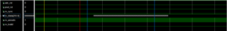
JMODE1,ILA observed sync signal is pulled low but xillnx IP core tdata has no data input (K28.5), when I set ADC R203 register to 0 (JSYNC_N = 0 ), IP core still has no K28.5 input.
The customer uses their own design board, the FPGA is 420T, the refclk and the reference clock of the FPGA is generated by LMK04828, the LMK connects the LMX2594 to output the ADC device clock and the reference clock. The oscilloscope can observe the generated clock signal. This is the signal captured by the ILA
Could you make any troubleshooting suggestions?
Register configuration:
assign cfg_mem[ 0] = { 15'h0000,8'hB0 };//reset
assign cfg_mem[ 1] = { 15'h0200,8'h00 };//Program JESD_EN=0 to stop the JESD204B state machine and allow setting changes.
assign cfg_mem[ 2] = { 15'h0061,8'h00 };//Program CAL_EN=0 to stop the calibration state machine and allow setting changes
assign cfg_mem[ 3] = { 15'h0201,8'h01 };//Program desired JMODE. JMODE=1
assign cfg_mem[ 4] = { 15'h0202,8'h1F };//Program desired KM1 value. KM1 = K-1
assign cfg_mem[ 5] = { 15'h0030,8'hFF };//1000mVpp
assign cfg_mem[ 6] = { 15'h0031,8'hFF };
assign cfg_mem[ 7] = { 15'h0032,8'hFF };//1000mVpp
assign cfg_mem[ 8] = { 15'h0033,8'hFF };
assign cfg_mem[ 9] = { 15'h0204,8'h02 };//Program SYNC_SEL as needed. Choose SYNCSE or Timestamp differential inputs and SCR.//SYNC_SEL =1 TMSTP
assign cfg_mem[ 10] = { 15'h0203,8'h00 };//
assign cfg_mem[ 11] = { 15'h0205,8'h00 };//// NORMAL 0: Test mode d
assign cfg_mem[ 12] = { 15'h0213,8'h07 };// Enable overrange, set overrange holdoff to max period 8*2^7 = 1024 samples 8*2^7 = 1024
assign cfg_mem[ 13] = { 15'h0048,8'h03 };// Set serializer pre-emphasis to 3
//assign cfg_mem[ 14] = { 15'h0060,8'h01 };// Input Mux Control Register 01:single input A ;02 single input B
assign cfg_mem[ 14] = { 15'h0029,8'h30 };
assign cfg_mem[ 15] = { 15'h0029,8'h70 };
assign cfg_mem[ 16] = { 15'h0029,8'h73 };
assign cfg_mem[ 17] = { 15'h0061,8'h01 };//Program CAL_EN=1 to enable the calibration state machine.
assign cfg_mem[ 18] = { 15'h0200,8'h01 };// Program JESD_EN=1 to re-start the JESD204B state machine and allow the link to re-start
assign cfg_mem[ 19] = { 15'h006C,8'h00 };//Set CAL_SOFT_TRIG low to reset calibration state machine
assign cfg_mem[ 20] = { 15'h006C,8'h01 };//Set CAL_SOFT_TRIG high to enable calibration
assign cfg_mem[ 21] = { 15'h02C0,8'h00 };
assign cfg_mem[ 22] = { 15'h02C2,8'h00 };
assign cfg_mem[ 23] = { 15'h02C1,8'h1F }
Best Regards,
Amy Luo


