Other Parts Discussed in Thread: ADS1260
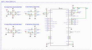
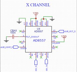
Hello. I am designing a load cell with ADS1235 as the ADC with a pre-amplification system using AD8557 as OPAMPS, and STM32F405RGT6 as uC for this system.
I can successfully measure and change gain settings using firmware libraries provided by TI for the ADS1235.
For my application, I need to calculate angle by measuring forces in 2 separate channels (X and Y), and the taring process is very critical to guarantee that the zeros are correctly found and I don't have any pre-charges on any of the channels before the calibration to successfully find the load coefficients.
I designed a taring function that looks like this:
void tare(float data[], long n_samples){
long tarebufferX[n_samples]{0}; //arrays to store X and Y channel values
long tarebufferY[n_samples]{0};
for(int i = 0; i<n_samples;i++){ //collects some trash values, to stabilize readings
tarebufferX[i] = data[0];
tarebufferY[i] = data[1];
}
for(int i = 0; i<n_samples;i++){ //collects the values from each channel to find mid point and use as the new "zero"
tarebufferX[i] = data[0];
tarebufferY[i] = data[1];
}
sort(tarebufferX,sizeof(tarebufferX)); //function to sort the data from smallest to biggest so I can access mid point and use median value as index for tare
sort(tarebufferY,sizeof(tarebufferY));
x_tared = tarebufferX[n_samples/2]; //use mid point for taring value instead of average
y_tared = tarebufferY[n_samples/2];
In this function I use the "data[]" array that is updated using the ADS1235 hardware interruption through DRDY pin, that looks like this:
void handleDRDY(){
data[selectedChannel] = adc.readData();
selectedChannel = !selectedChannel;
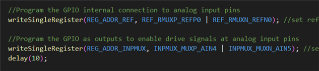
adc.setReference(selectedChannel);
adc.setChannel(selectedChannel);
}
Where I basically read the data, change channel/references from 0 to 1 and 1 to 0, and read the data again when DRDY is available.
the x_tared and y_tared values from tare() are then subtracted by the output, like:
data[0] = data[0] - x_tared;
data[1] = data[1] - y_tared;
My signal is plotted through Serial port at 80Hz, but the data[] array is updated at the interrupt frequency of the hardware interrupt.
Before taring, with ADC gain set to 1 and registers are set as follows, I get a signal like this
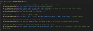
Before taring, with ADC gain set to 1 and registers are set as follows, I get a signal like this
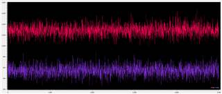
Where CHX = channel 0 and CHY = channel Y
after I execute a tare using 1000 samples as input, the signal does this:
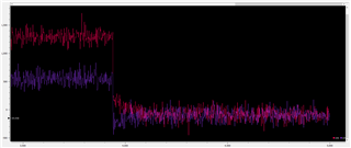
after I execute a tare using 1000 samples as input, the signal does this:
In which it takes some seconds to stabilize and I get readings around -150 ADC values. Some times more some times less, but never really close to zero. Sometimes the values from CHX diverge a lot from CHY (ex: chx go to 100 and chy go to -400), which kills my calibration process. I tried detaching the interrupt before starting the process and attaching it later again after the function is executed, but the results are even worse. In higher gain settings the difference from 0 is even worse (i get 2000 or more as baseline after tare).
When we are checking the signal both x and y are stable so the tare should work fine.
Am I calling the function in a wrong way that maybe is electrically destabilizing the ADC so during the tare() function the readings are not accurate? Is there any way in which I may do this differently? I kindly wait for your response.
Thank you very much for the support,
Am I calling the function in a wrong way that maybe is electrically destabilizing the ADC so during the tare() function the readings are not accurate? Is there any way in which I may do this differently? I kindly wait for your response.
Thank you very much for the support,
João