Other Parts Discussed in Thread: ADS1292, ADS1298R, ADS1298RECGFE-PDK
Hello TI experts,
My customer uses ADS1292R for their own product, and they have a problem.
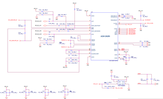
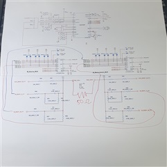
They use P4(IN1P) and P31(RESP_MODP/IN3P) to measure human body impedance, and they connect 50ohm between these 2 pins when the device is not used.
the problem is, because of the SMPS noise, this 50 ohm is measured little different. (from 48 to 54 ohm)
do you have any idea to eliminate this noise by adding additional schematic on ADS1292R?
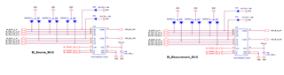
I attach a schematic for your convenience.
(they tested 64KHz and 32KHz on ADS1292R, and applied 7Hz low pass filter.-> does not changed.)
(also they tested PWM 100KHz and PFC 100KHz and 90KHz -> does not changed.)
Please check this issue. Thanks.
Best regards,
Chase